Mesh generators#
The Mesh class collects all informations related to a mesh, mainly:
the list of nodes of the mesh, say a list of
Point,the list of elements of the mesh, say a list of
GeomElementrefering either to aMeshElementor to a side ofGeomElement,the list of geometric domains, say a list of
GeomDomainhandling a list ofGeomElement.
The MeshElement object gathers all the informations about a mesh element (shape, node numbering, side numbering, … )
while the GeomElement class acts as an interface with a MeshElement or a side of a GeomElement.
Most of all meshes are produced using the generic Mesh constructor:
Mesh(geometry, key_1=value_1, key_2=value_2, ….)
where geometry is any Geometry object and key_i is one of the following keys:
_generator: type of mesh generator, eitherstructured,subdiv,gmsh,gmshOCorfromParameterization. Generator allowed depends on geometry and the availability of OpenCascade._shape: type of element to be used in mesh, eithersegment,triangle,quadrangle,tetrahedron,hexahedron,prismorpyramid. Types allowed depends on the geometry to be meshed and the generator used._order: order of elements used to mesh the geometry, works only with the Gmsh generator up to order 5._split_direction: tells to structured mesh tool in 2D how to split each quadrangle into 2 or 4 triangles (left(default),right,alternate,random,cross)._pattern: tells to Gmsh to mesh in astructuredway or in aunstructuredway (default)._refinement_depth: refinement depth in subdivision mesh generator._name: a mesh name.
Hint
Using a n-1 dimensionnal shape type for a n-dimensionnal geometry leads to a mesh of the boundary of the geometry.
Structured internal meshing tools#
XLiFE++ offers some internal tools to mesh ‘cartesian’ geometries in a structured way: Segment, Parallelogram (Rectangle, Square),
Parallelepiped (Cuboid, Cube) : nodes are distributed evenly in each direction.
For Segment and Parallelogram geometries, the structured mesh tool is used by default, producing segment or triangle partitions (P1) from quadrangle partitions.
XLiFE++ offers several ways of splitting quadrangles into triangles, driven by the key _split_direction and values: left (default), right, alternate, random and cross.
For instance, the following mesh commands are available:
Segment s(_v1=0., _v2=1., _nnodes = 10);
Mesh ms(s);                          // structured mesh tool

Rectangle R(_xmin=0, _xmax=1, _ymin=1, _ymax=3, _nnodes={6,10});
Mesh mq(R,_shape=quadrangle);         // Q1 structured mesh tool
Mesh m(R);                            // P1 structured mesh tool (left splitting)
Mesh ml(R,_split_direction=left);     // same as previous
Mesh mr(R,_split_direction=right);    // P1 structured mesh with right splitting
Mesh ma(R,_split_direction=alternate);// P1 structured mesh with alternate splitting
Mesh mc(R,_split_direction=cross);    // P1 structured mesh with cross splitting
Mesh mg(R,_split_direction=random);   // P1 structured mesh with random splitting

Fig. 65 Mesh of a rectangle with respectively left, right, alternate, cross and random splitting#
For Parallelepiped geometry, the structured mesh tool is used by default only if the _shape is specified as hexahedron.
Otherwise, if the _generator key is not specified, the subdivision mesh tool is used (see the next section). If the _generator key is specified as structured,
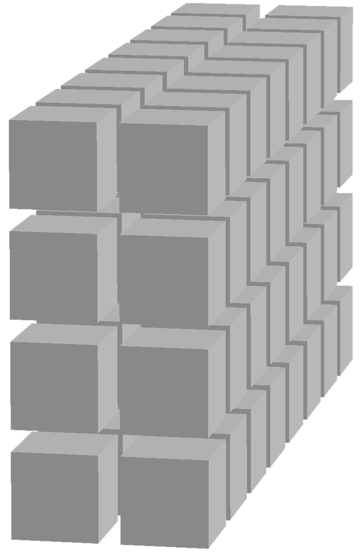
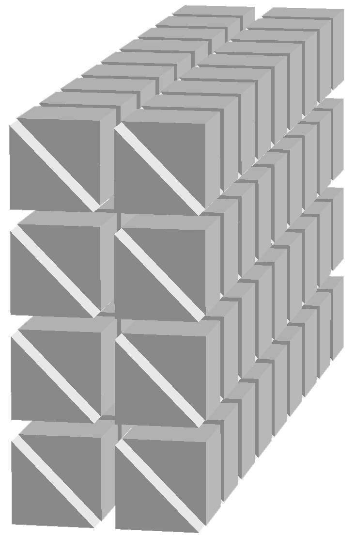
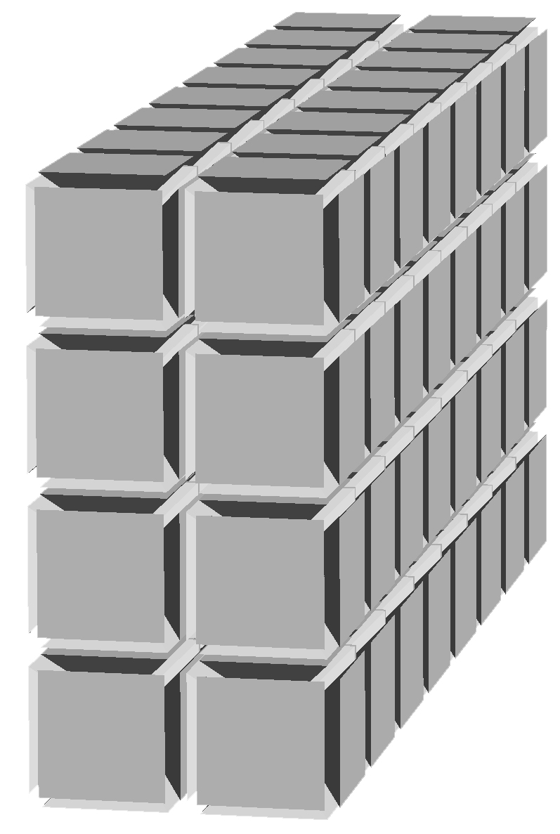
a structured mesh may be generated using prism (extrusion) or pyramid (splitting hexahedron into pyramids):
Cuboid C(_xmin=0, _xmax=1, _ymin=1, _ymax=3, _zmin=1, _zmax=5, _nnodes={3, 5, 9});
Mesh mh(C, _shape=hexahedron);                    // structured mesh with hexahedron
Mesh mp(C, _generator=structured, _shape=prism);  // structured mesh with prisms
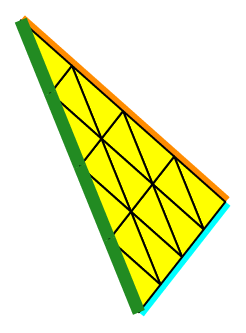
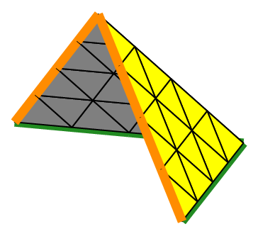
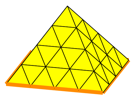
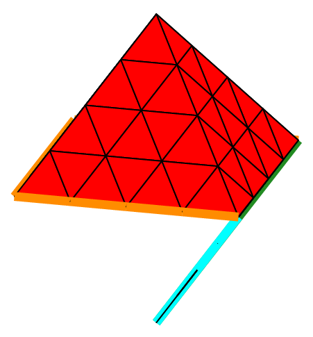
Mesh my(C, _generator=structured, _shape=pyramid);// structured mesh with pyramids
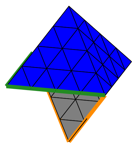
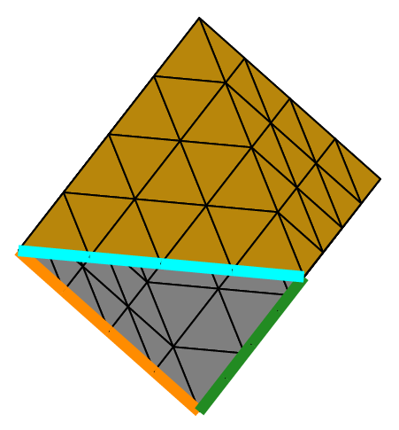
Fig. 66 Structured mesh of a parallelepiped with hexahedra, prisms and pyramids (shrink view).#
Note
An other way to mesh a parallelepiped with pyramids is to use the split funcion:
Mesh mQ1(C, _shape=hexahedron);// structured mesh with hexahedron
Mesh mPy=split(mQ1,_pyramid);  // mesh with hexahedron split into pyramids
It gives the same mesh as those obtained with the constructor.
Meshing boundaries of such 2D/3D geometries can also be done by specifying the shape type to be used (segment, triangle or quadrangle):
Rectangle R(_xmin=0, _xmax=1, _ymin=1, _ymax=3, _nnodes={6,10});
Mesh mb(R,_shape=segment);     // structured mesh of rectangle boundary

Cuboid C(_xmin=0, _xmax=1, _ymin=1, _ymax=3, _zmin=1, _zmax=5, _nnodes={3, 5, 9});
Mesh mP1b(cu,_generator= structured,_shape =_triangle);  //P1 mesh of cuboid boundary
Mesh mP1b(cu,_generator= structured,_shape =_triangle,_split_direction=cross);
Mesh mQ1b(cu,_generator= structured,_shape =_quadrangle);//Q1 mesh of cuboid boundary
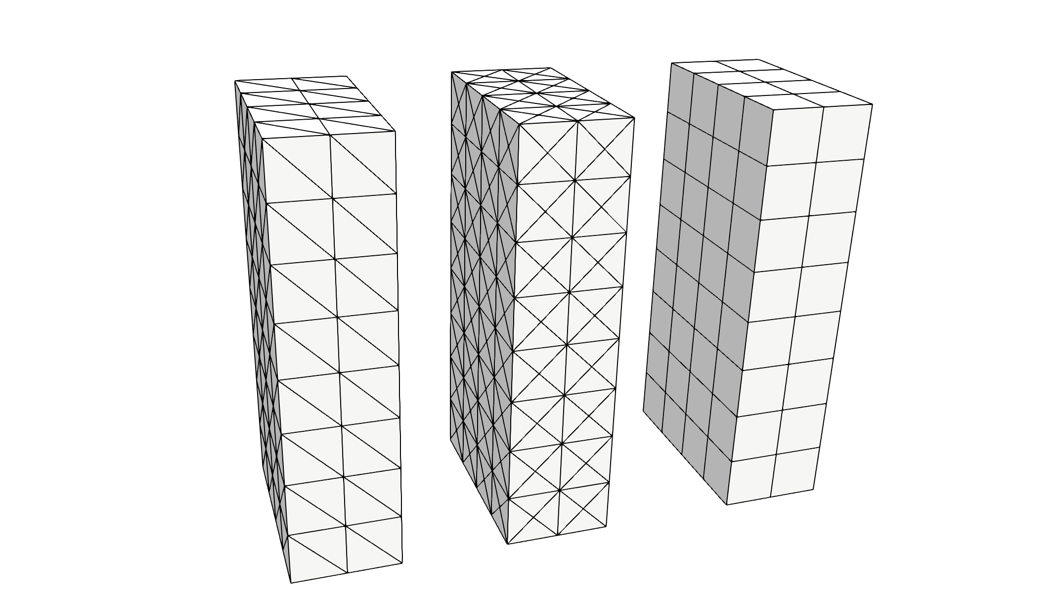
Fig. 67 Structured mesh of cuboid boundary with triangles (left and cross splitting) and quadrangles.#
Internal meshing subdivision generator#
When the subdivision algorithm is chosen (_generator=subdiv), one can create a mesh of any order based on the following volumetric geometries:
The sphere meshed by tetrahedra,
the cube meshed by tetrahedra or hexahedra,
the cone or truncated cone, which may be a cylinder, meshed by tetrahedra or hexahedra.
The following surface geometries are also handled:
The boundary of the sphere meshed by triangles,
the boundary of the cube meshed by quadrangles,
the boundary of the cone or truncated cone meshed by triangles or quadrangles,
the disk meshed by triangles or quadrangles,
mesh built from an initial set of triangles or quadrangles in 2D or 3D.
The generator consists in starting from an initial mesh, a kind of “seed” mesh, namely a set of elements, and builds the mesh by subdividing each of them by cutting each edge in the middle until a prescribed so-called “subdivision depth” is reached. A subdivision depth equal to 0 gives a mesh reduced to the initial mesh. A triangle and a quadrangle are subdivided into 4 pieces; a tetrahedron and a hexahedron is subdivided into 8 pieces. Thus, at each subdivision, the number of elements of the mesh is multiplied by 4 for a surface mesh, by 8 for a volumetric one, and the characteristic dimension of the elements is halved.
One has to declare an object of type Geometry, more precisely of type Sphere, Ball, Cube, RevTrunk, RevCone, RevCylinder, Disk or SetOfElems using one of the available constructors, e.g.:
SetOfElems(const std::vector<Point>& pts, const std::vector<std::vector<nNumber> >& elems, const std::vector<std::vector<nNumber> >& bounds, const ShapeType esh, const Number nbsubdiv=1);
Mesh of a ball (or sphere) with tetrahedra#
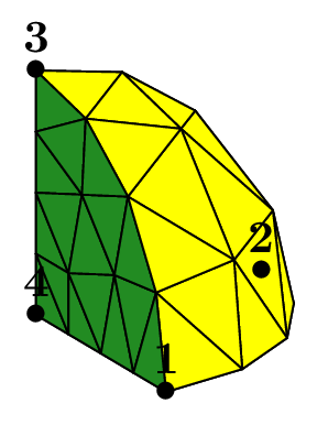
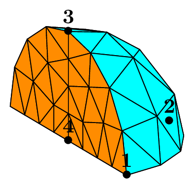
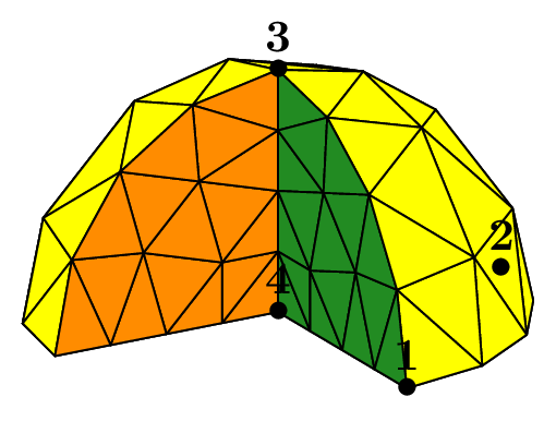
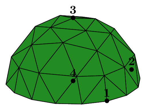
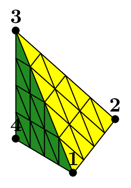
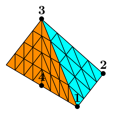
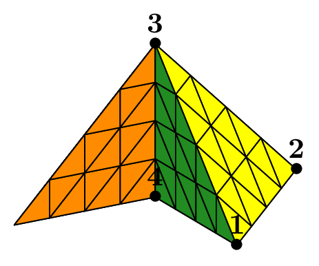
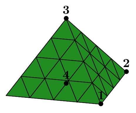
The seed of the mesh consists of a unique tetrahedron inside each octant of the cartesian axes.
We can choose the number of octants to be taken into account, from 1 to 8, to mesh different portions of the sphere.
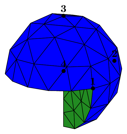
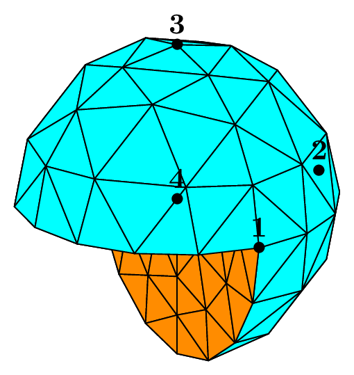
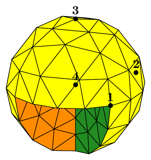
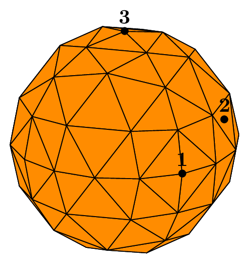
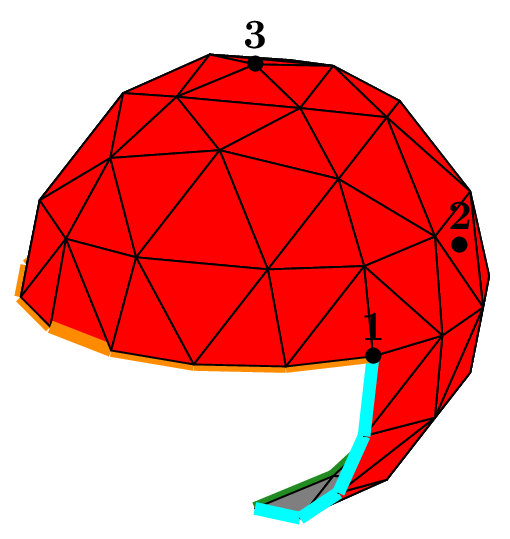
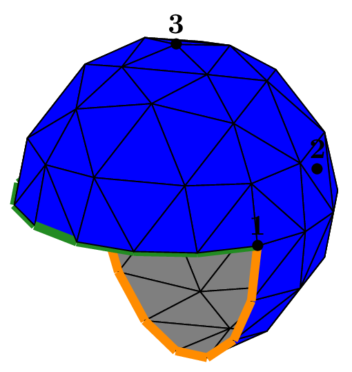
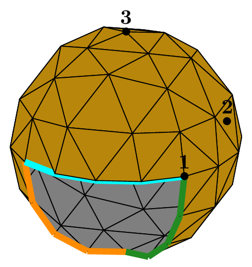
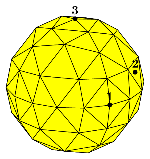
The figure Fig. 68 shows this in the case of a subdivision depth equal to 2. Each figure corresponds to the result of the following code, using the unit sphere and _nboctants varying from 1 to 8:
Number order = 1, nbpts=5, meshType = 1;
Ball sph(_center=Point(0.,0.,0.), _radius=1., _nboctants=nboctants, _nnodes=nbpts, _type=meshType);
Mesh m(sph, _order=order, _generator=subdiv);
Each color corresponds to a different boundary domain.
The default value of the key type is 1; setting it to 0 leads to a so-called flat mesh, where the points created during the algorithm are not projected onto the sphere,
thus keeping the shape of the initial mesh. We can see the effect of this choice on figures representing the “flat ball”.
Fig. 68 Volumic meshes of the different portions of the ball according to the number of octants#
Fig. 69 Volumic meshes of the different portions of the “flat ball” according to the number of octants#
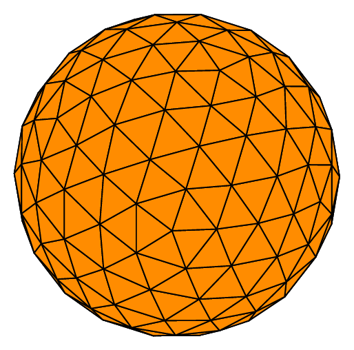
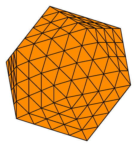
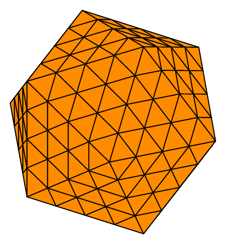
If we specifically want the mesh inside the whole sphere, it can be useful to start from an icosahedron because of its geometric properties, which lead to a more isotropic mesh than the one based on the 8 octants of the space. On the other hand, there will be no interface planes defined.
In order to activate this option, the key _nboctants should simply be set to 0. The following code gives the figure Fig. 70, which shows both the round and flat results of the algorithm:
Ball sph(_center=Point(0.,0.,0.), _radius=1., _nboctants=0, _nnodes=5);
Mesh m(sph, _generator=subdiv);

Ball sph2(_center=Point(0.,0.,0.), _radius=1., _nboctants=0, _nnodes=5, _type=0);
Mesh m2(sph2, _generator=subdiv);
Fig. 70 Volumic meshes starting from an icosahedron#
Mesh of a cube with tetrahedra or hexahedra#
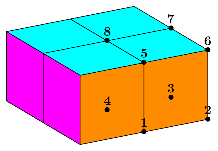
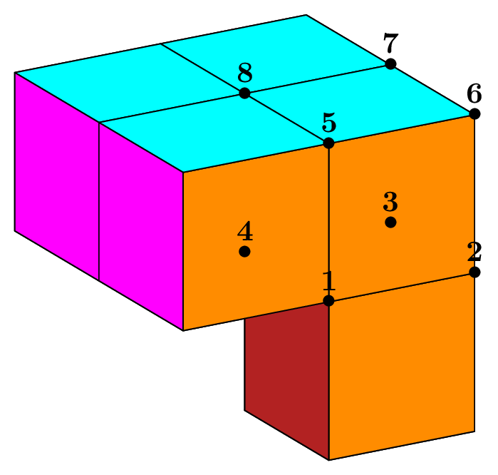
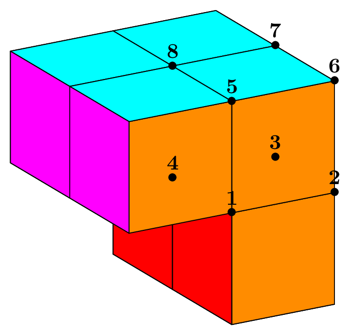
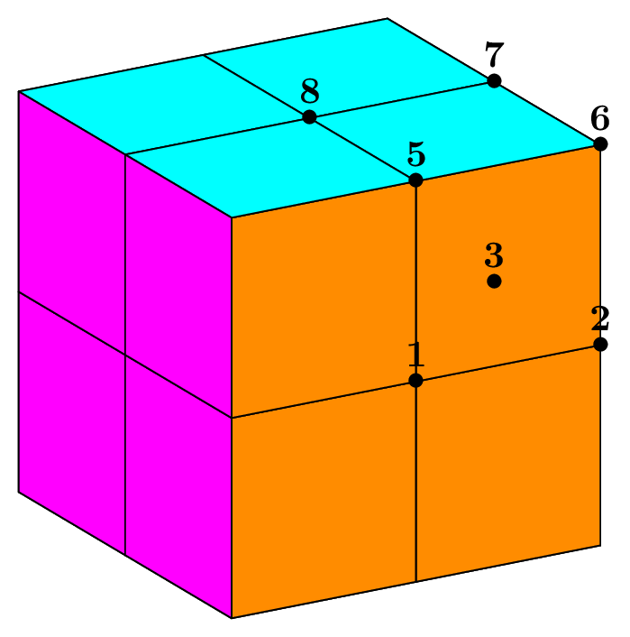
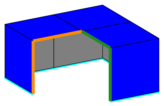
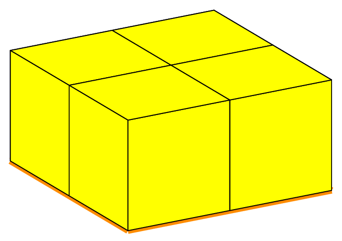
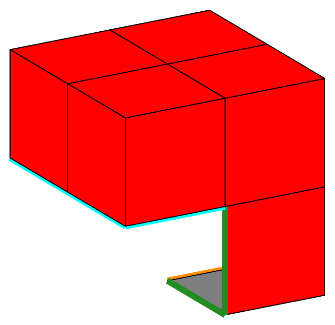
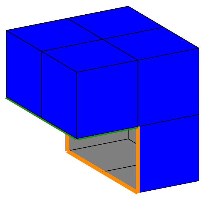
The selection of the octants is also used in the case of the cube as shown on the figure Volumic meshes of the different portions of the cube according to the number of octants.,
which is the result of the following code, with no subdivision and _nboctants varying from 1 to 8:
Cube cube(_center=Point(0.,0.,0.), _length=2., _nboctants=nboctants, _nnodes=2);
Mesh m(cube, _shape=hexahedron, _generator=subdiv);
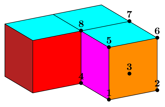
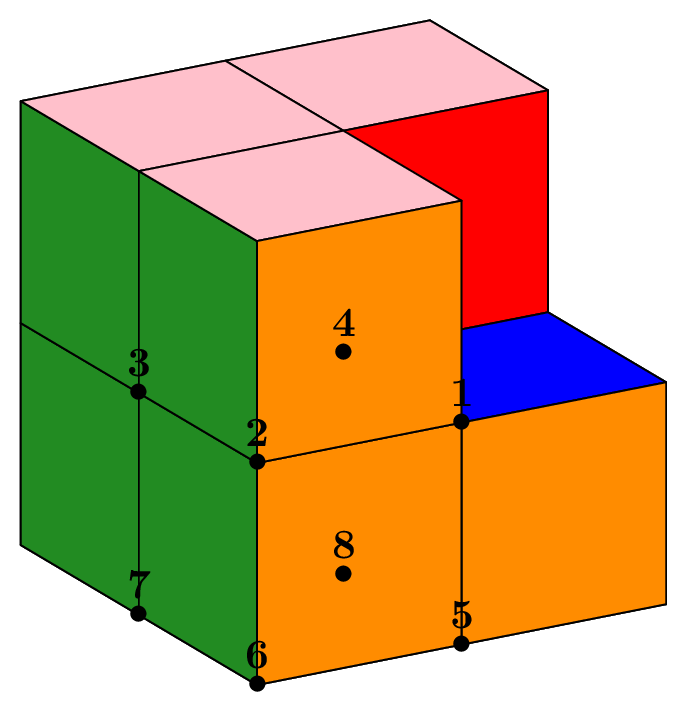
Notice that the edge length of the total cube is 2, so that the cube in the first octant is the so-called unit cube. Apart the choice of the mesh element (tetrahedron or hexahedron), the main interest of this case is the easy creation of a L-shape domain (3 octants) and the Fichera corner (7 octants), classical benchmark problems in the analysis of corner and edge singularities. It is shown on figure Fig. 71 in an unsual position; in order to put the missing cube in the first octant, one must apply a rotation, which is done by the following code:
Cube cube(_center=Point(0.,0.,0.), _length=2., _nboctants=7, _nnodes=2);
cube.rotate3d(Point(0.,0.,0.), 1.,0.,0., pi_);
Mesh m(cube, _shape=hexahedron, _generator=subdiv);
The two additional arguments define the rotation of angle 180 degrees around the first axis (X-axis); the result is shown on the next figures, at the last position (bottom right). If necessary, one can specify one or two more rotations in the form (angle, naxis). The angle is to be given in degrees and naxis defines the rotation axis: it is the number of the absolute axis, thus 1, 2 or 3.
Fig. 71 Volumic meshes of the different portions of the cube according to the number of octants.#
Mesh of a cylinder with tetrahedra or hexahedra#
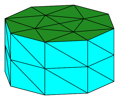
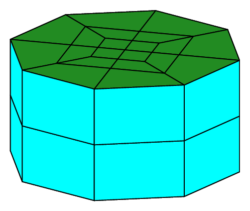
The subdivision algorithm can handle the case of a cylinder of revolution, whose axis is defined by two points P1 and P2, and delimited by the two planes containing the two points and orthogonal to the axis. As an example, we consider the “unit” cylinder of radius 1 and height 1. The following code produces the first two meshes shown on figure Fig. 72:
Point P1(0.,0.,0.), P2(0.,0.,1.);
RevCylinder cyl1(_center1=P1, _center2=P2, _radius=1., _nnodes=3);
Mesh mT(cyl, _generator=subdiv);
Mesh mH(cyl, _shape=hexahedron, _generator=subdiv);
Fig. 72 Volumic meshes of the “unit” cylinder with tetrahedra and hexahedra#
Obviously, this is a poor approximation of the cylinder. To get a more accurate description, the user can then increase the number of elements (greater value of nbsubdiv) or increase the approximation order (or both).
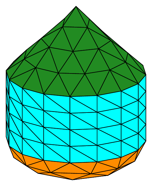
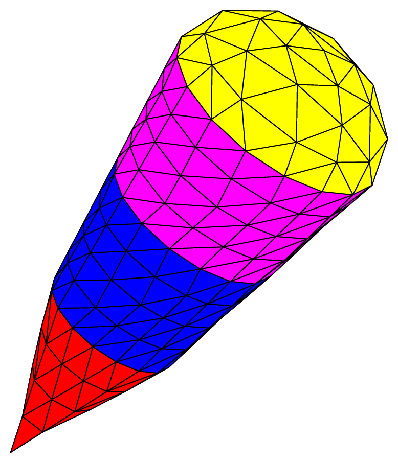
In the case of a tetrahedron mesh, each end-plane may be covered by a “hat”, that is to say a solid whose shape may be a cone or an ellipsoid.
The last drawing of figure Fig. 72 shows such a configuration, with an ellipsoid on the side of P1 (keyword gesEllipsoid) whose apex is at radius/2 from the basis of the cylinder, and a cone on the side of P2 (keyword gesCone)
whose apex is at radius from the other basis of the cylinder. It is obtained by the following code:
RevCylinder cyl2e(_center1=Point(0.,0.,0.), _center2=Point(0.,0.,1.), _radius=1., _end1_shape=gesEllipsoid, _end1_distance=radius/2, _end2_shape=gesCone, _end2_distance=radius, _nnodes=5);
Mesh P1VolMeshTetCylE(cyl2e, _generator=subdiv);
Two other shapes exist: gesNone and gesFlat. They have an equivalent meaning in the case of a solid body.
They are the default value and indicate that no “hat” should be added at the corresponding end.
Mesh of a cone or a truncated cone with tetrahedra or hexahedra#
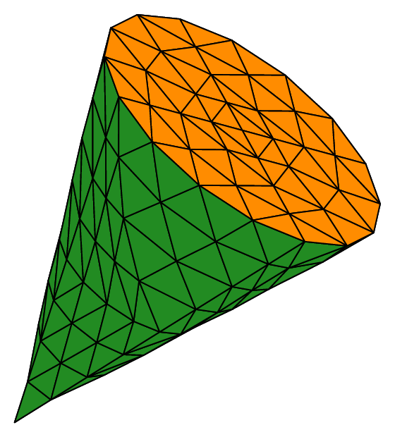
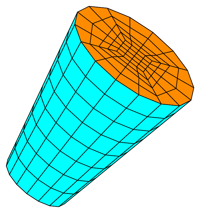
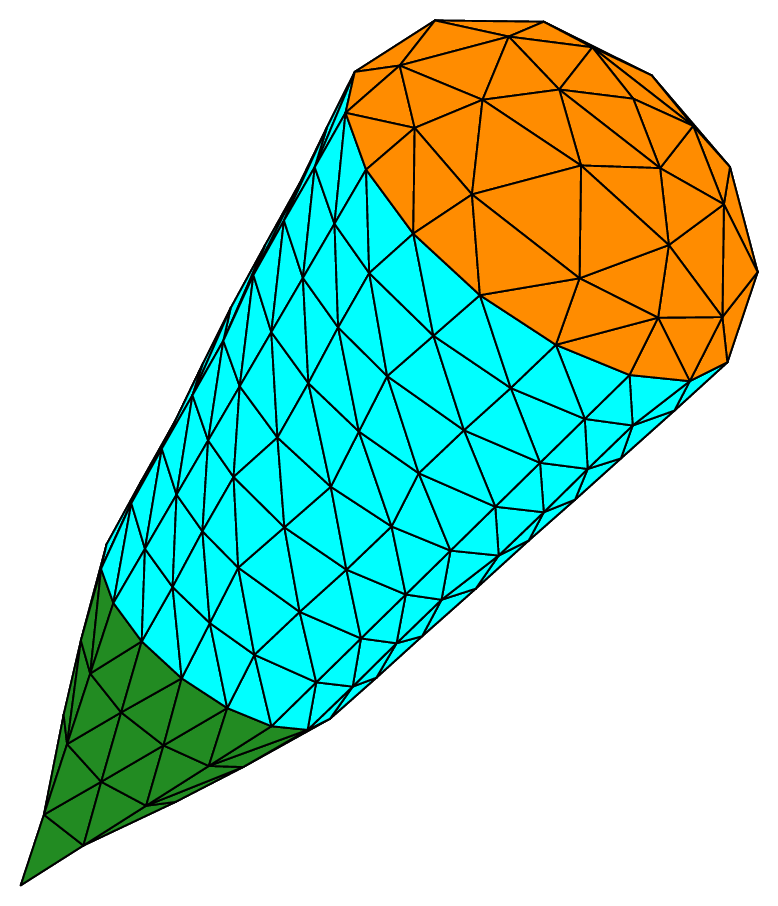
A truncated cone of revolution is defined by an axis, given by two points P1 and P2, delimited by the two planes containing the two points and orthogonal to the axis. The two circular sections are defined by two radii. The following code produces the first two meshes shown on figure Fig. 73:
Point P1(-1.,-1.,0.), P2(0.,0.,2.);
RevCone cone(_center=P2, _radius=1., _apex=P1, _nnodes=5);
Mesh mT(cone, _generator=subdiv);

RevTrunk cone2(_center1=P1, _radius1=0.5, _center2=P2, _radius2=1., _nnodes=5);
Mesh mH(cone2, _shape=hexahedron, _generator=subdiv);
The number of slices is 0, which means that a suitable default value is automatically computed from the length of the axis and the radii. The first object is a “true” cone since one radius is 0; it can be meshed exactly with tetrahedra. Using hexahedra for this geometry is not advised since the elements will be degenerated at the apex of the cone. Moreover, the radius cannot be 0, it should be at least 1.e-15, leading to a “near true” cone, but with highly degenerated hexahedra close to the apex. Hexahedra are more suitable to build a trucated cone; an example is shown on the middle drawing of the figure Fig. 73.
Fig. 73 Volumic meshes of the cone and truncated cone with tetrahedra and hexahedra#
The following code produces the last mesh shown on figure Fig. 73:
RevTrunk cone1(_center1=Point(-1.,-1.,0.), _radius1=0.6, _center2=Point(0.,0.,2.), _radius2=1., _end1_shape=gesCone, _end1_distance=1.5, _end2_Shape=gesEllipsoid, _end2_distance=0.7, _nnodes=5);
Mesh mTE(cone1, _generator=subdiv);
In the same way as for the cylinder, the truncated cone can be “covered” with a solid. This is only available for a mesh made of tetrahedra. We show a cone and an ellipsoid put at each end of a truncated cone, respectively on the side of P1 and on the side of P2.
Mesh of a sphere with triangles#
The same logic described previously for a mesh of tetrahedra applies here for a mesh of triangles. The following code leads to meshes of the boundary of the unit sphere, and the result is shown on the following figure:
Ball sph(_center=Point(0.,0.,0.), _radius=1., _nboctants=nboctants, _nnodes=5);
Mesh m(sph, _shape=triangle, _generator=subdiv);
Fig. 74 Surfacic meshes of the different portions of the boundary of the sphere according to the number of octants#
Again, if the key _type is set to 0, we get the “flat” version of the meshes, i.e. the
meshes obtained from the subdivision of the nboctants initial triangles (see next figure).
Fig. 75 Surfacic meshes of the different portions of the “flat sphere” according to the number of octants.#
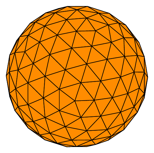
If we specifically want the mesh of the whole sphere, it can be useful to start from an icosahedron because of its geometric properties, which lead to a more isotropic mesh than the one based on the 8 octants of the space. On the other hand, there will be no interface planes defined.
In order to activate this option, the key _nboctants should simply be set to 0. The following code gives the figure Fig. 76, which shows both the round and flat results of the algorithm:
nboctants = 0, nbpts=5; meshType = 1;
Ball sph(_center=Point(0.,0.,0.), _radius=1., _nboctants=0, _nnodes=5);
Mesh m(sph, _shape=triangle, _generator=subdiv);

Ball sph2(_center=Point(0.,0.,0.), _radius=1., _nboctants=0, _nnodes=5, _type=0);
Mesh m2(sph2, _shape=triangle, _generator=subdiv);
Fig. 76 Surfacic meshes starting from an icosahedron#
Mesh of a cube with quadrangles#
We can obtain the mesh of the surface of a cube, or part of it, with quadrangles, by using the same logic described just above for the sphere. Consider the following code:
Cube cube(_center=Point(0.,0.,0.), _length=2., _nboctants=nboctants, _nnodes=2);
Mesh m(cube, _shape=quadrangle, _generator=subdiv);
Letting _nboctants vary from 1 to 8, then 0, lead to the objects shown on figure below.
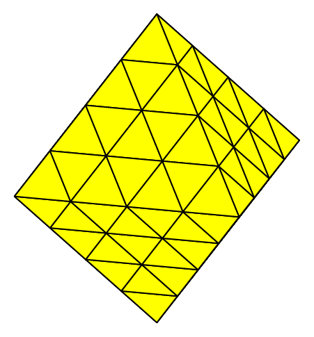
Fig. 77 Surfacic meshes of the different portions of the cube according to the number of octants#
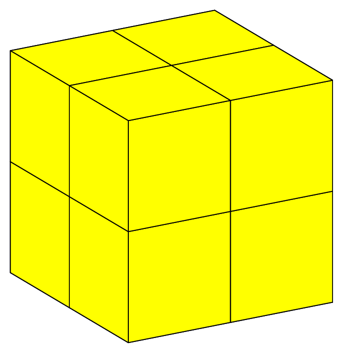
The last object (_nboctants=0) is the simplest mesh of a cube made of 6 quadrangles (squares here). By subdividing it once, we get the previous yellow object (_nboctants=8) made of 24 quadrangles.
Mesh of a cone or a truncated cone with triangles#
We can build a mesh of the surface of a truncated cone with triangles. The following code produces the first two drawings of the figure Surfacic meshes of a cylinder:
Point P1(0.,0.,0.), P2(0.,0.,1.);
RevCylinder cyl1(_center1=P1, _center2=P2, _radius=1., _nnodes=3);
Mesh mT(cyl, _shape=triangle, _generator=subdiv);

RevCylinder cylE(_center1=P1, _center2=P2, _radius=1., _end1_shape=gesFlat, _end1_distance=0., _end2_shape=gesNone, _end2_distance=0., _nnodes=5);
Mesh mTE(cylE, _shape=triangle, _generator=subdiv);
Fig. 78 Surfacic meshes of a cylinder#
Point P1(-1.,-1.,0.), P2(0.,0.,2.);
RevTrunk cone3(_center1=P1, _radius1=0.5, _center2=P2, _radius2=1., _end1_shape=gesNone, _end1_distance=0., _end2_shape=gesFlat, _end2_distance=0., _nnodes=5);
Mesh mT(cone3, _shape=triangle, _generator=subdiv);

RevTrunk cone1(_center1=P1, _radius1=0.5, _center2=P2, _radius2=1., _end1_shape=gesCone, _end1_distance=1.5, _end2_shape=gesEllipsoid, _end2_distance=0.7, _nnodes=5);
Mesh mTE(cone1, _shape=triangle, _generator=subdiv);
Fig. 79 Surfacic meshes of a truncated cone#
Mesh of a cone or a truncated cone with quadrangles#
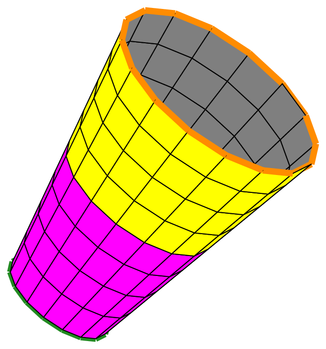
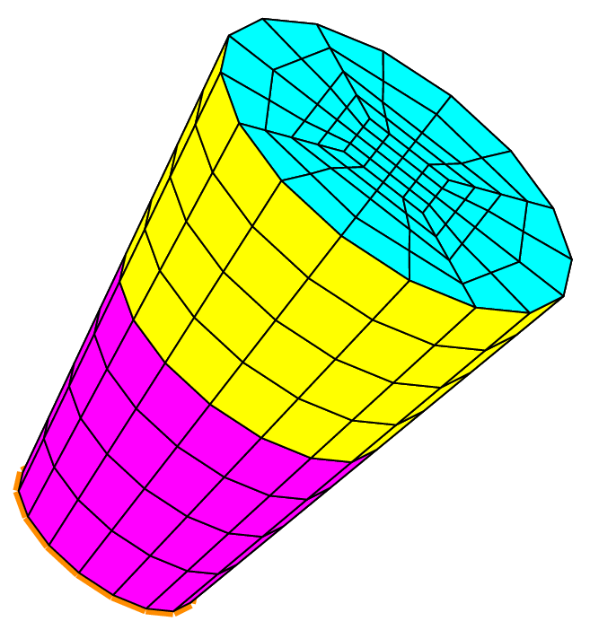
We can build a mesh of the surface of a truncated cone with quadrangles. The following code produces the first two drawings of the figure Surfacic meshes of a cone and a cylinder:
Point P1(-1.,-1.,0.), P2(0.,0.,2.);
RevTrunk cone2(_center1=P1, _radius1=0.5, _center2=P2, _radius2=1., _nnodes=5);
order=1;
Mesh mQ(cone2, _shape=quadrangle, _generator=subdiv);

RevTrunk cone3(_center1=P1, _radius1=0.5, _center2=P2, _radius2=1., _end1_shape=gesNone, _end1_distance=0., _end2_shape=gesFlat, _end2_distance=0., _nnodes=5);
Mesh mQF(cone3, _shape=quadrangle, _generator=subdiv,  _name="mQF");
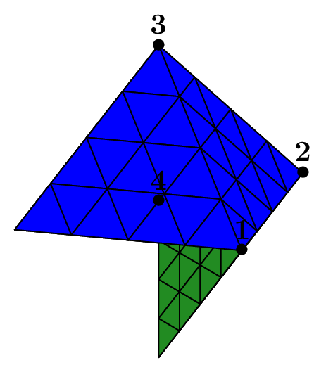
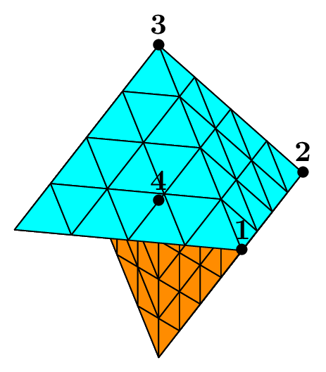
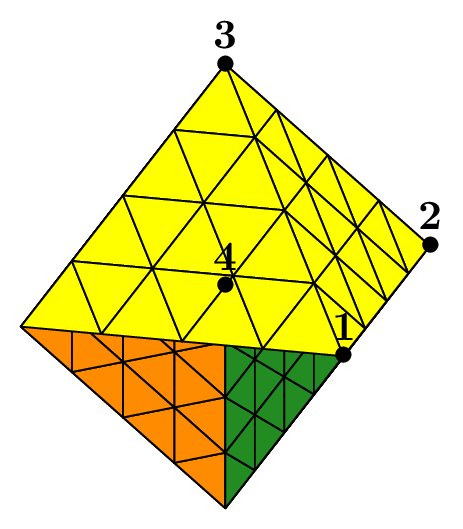
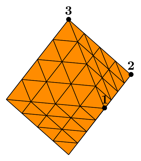
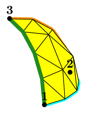
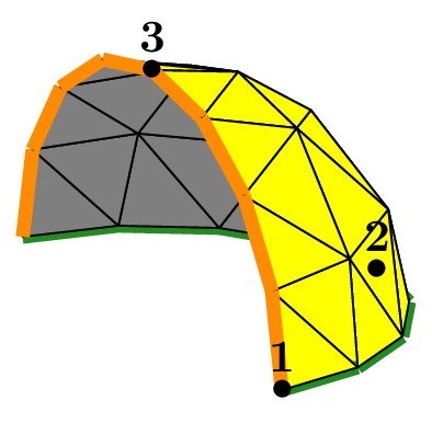
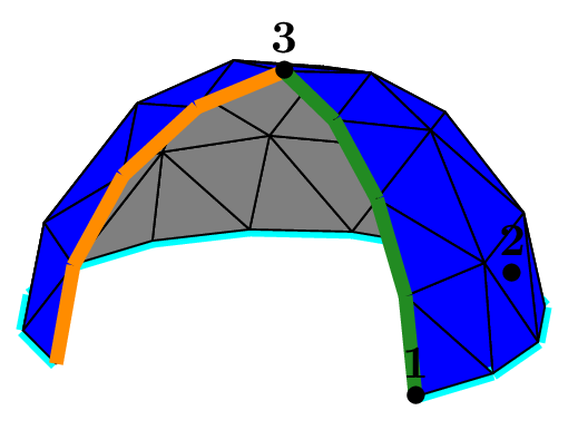
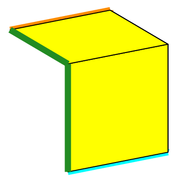
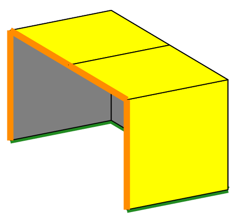
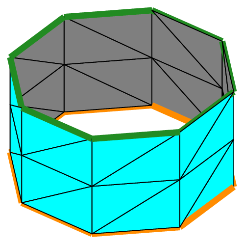
The left truncated cone is opened at both ends (this is the default); thus it has two boundaries shown in green (bottom) and orange (top). The object cone2 is the same as the one used previously to make the mesh of hexahedra (see figure Fig. 73).
The second drawing shows the same object bearing a “lid” on its top (on the side of P2). Indeed, such a truncated cone may be closed at one or both ends by a plane “lid”. This is obtained by specifying the geometric end shape to be used at each end: gesNone means that the cone is left opened, which is the default behaviour, and gesFlat means that a plane “lid” is requested.
The objet proposed in this example has thus one boundary at its other end (on the side of P1), shown as an orange line.
The result of the instruction mQF.printInfo(); is the following:
Mesh mQF; (cone - Quadrangle mesh)
space dimension : 3, element dimension : 2
Geometry   of shape type revolution volume based on cone of dimension 3,
BoundingBox [-1.45412,0.908248]x[-1.45412,0.908248]x[-0.288675,2.57735], names of variable : x, y, z
number of elements : 208, number of vertices : 217, number of nodes : 217, number of domains : 5
domain number 0: Omega (whole domain)
domain number 1: Sigma_1 (End subdomain on the side of end point 2)
domain number 2: Sigma_2 (Slice 1)
domain number 3: Sigma_3 (Slice 2)
domain number 4: Kappa_1 (Boundary: End curve on the side of end point 1)
Fig. 80 Surfacic meshes of a cone and a cylinder#
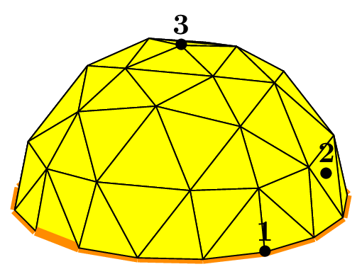
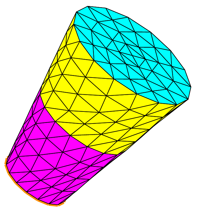
The last drawing shows the surfacic mesh of a cylinder, since it is a particular kind of cone. The cylinder is the same as the one shown on the following figure. The code that produces this mesh is:
Point P1(0.,0.,0.), P2(0.,0.,1.);
RevCylinder cyl(_center1=P1, _center2=P2, _radius=1., _nnodes=3);
Mesh mQCyl(cyl, _shape=quadrangle, _generator=subdiv);
The cylinder is opened at both ends and thus has two boundaries shown as a green line and an orange line.
Mesh of a disk or a section of a disk#
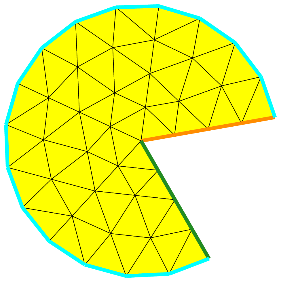
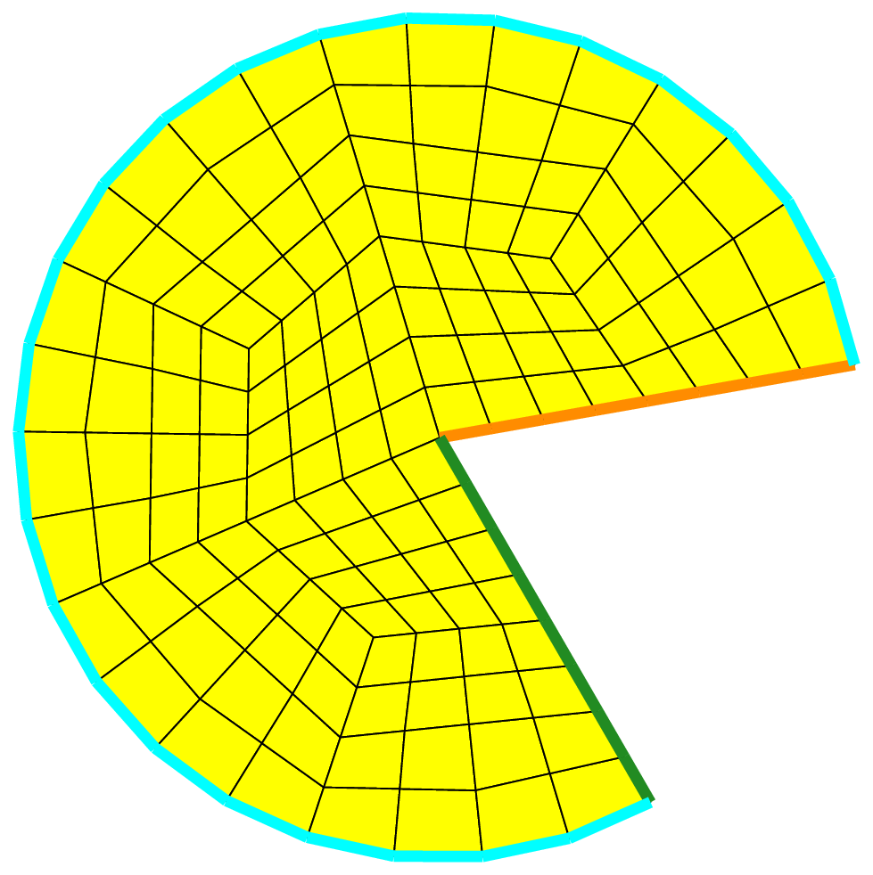
We can build the mesh of a disk or a section of a disk, with triangles or quadrangles. Using the following code, we get the result shown on the following figure.
Disk pdisk(_center=Point(0.,1.), _radius=2., _angle1=10., _angle2=300., _nnodes=5);
Mesh meshTriDisk(pdisk, _generator=subdiv);
Mesh meshQuaDisk(pdisk, _shape=quadrangle, _generator=subdiv);
Fig. 81 Meshes of a portion of disk with triangles and quadrangles#
Mesh from a set of triangles or quadrangles#
This possibility is designed to build a mesh starting from an elementary set of elements. Generally, this initial mesh is build “manually”. This gives a flexible mean to create a mesh which cannot be obtained with another constructor, but without having to resort to the help of a more complicated solution (like an external mesh generator in particular).
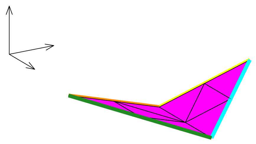
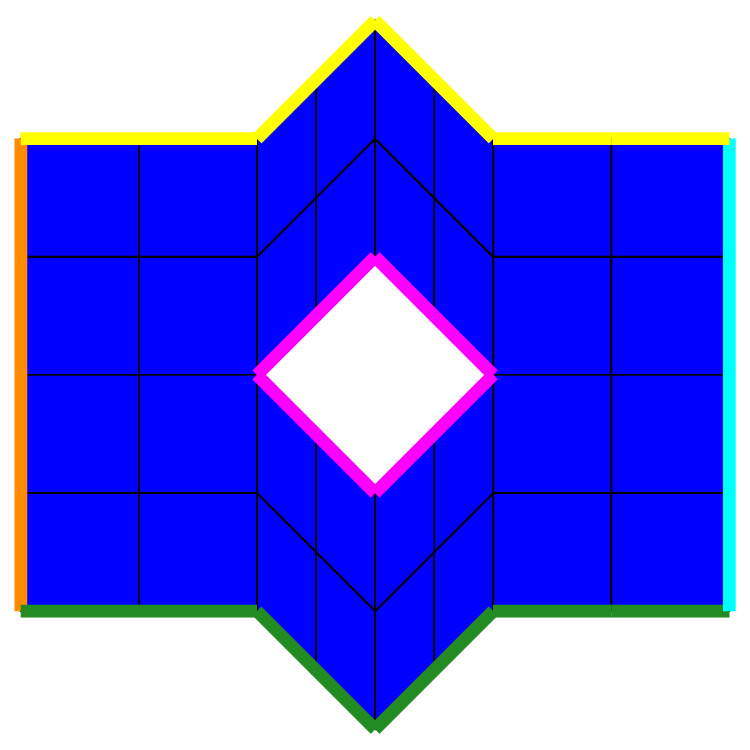
Such meshes can be made in 2D or in 3D with triangles or quadrangles. The following figure shows two examples, in 3D with triangles, in 2D with quadrangles on a domain with a hole.
Fig. 82 Meshes from initial set of triangles and quadrangles.#
The program that produces it looks like the following:
...
SetOfElems sot(tpts, telems, tbounds, triangle, nbsubdiv);
Mesh mT(sot, _generator=subdiv);
SetOfElems soq(qpts, qelems, qbounds, quadrangle, nbsubdiv);
Mesh mQ(soq, _shape=quadrangle, _generator=subdiv);
The mesh of triangle is based on an initial set of 2 triangles \(\{1,2,3\}\) and \(\{1,4,2\}\), stored in the vector elems. The 4 points are Point(0.,0.,0.), Point(1.,0.,0.), Point(0.,1.,0.3), Point(0.,-1.,0.3)
stored in the vector tpts. Four boundaries are defined.
A boundary is simply defined by the list of point numbers lying on it, in any order. Thus, here, the four boundaries are \(\{1,4\}, \{4,2\}, \{2,3\}\) and \(\{1,3\}\);
they are stored in the vector tbounds. The same apply for the set of quadrangles.
GMSH generator#
Using the Gmsh interface to define meshes allows to define more canonical geometries than both previous generators:
Segments, ellipses, circles, elliptical or circular arcs as 1D geometries;
Quadrangles, rectangles, squares, disks, elliptical surfaces, spheres, ellipsoids, triangles as 2D geometries with either triangular or quadrangular mesh elements;
Hexahedra, parallelepipeds, cubes, balls, tetrahedra, cylinders, prisms, pyramids as 3D geometries with either tetrahedral or hexahedral mesh elements.
When using the Gmsh generator , 2 files are generated in the working directory:
xlifepp_script.geo-
This is the input file of Gmsh. To simplify its writing, XLiFE++ provides a macro file included in this one. Looking at this file, shows a very elegant way to define meshes with Gmsh.
xlifepp_script.msh-
This is the real mesh file, generated by a system call to Gmsh from the .geo file. This file is loaded by XLiFE++.
More complicated geometries (the so-called “composite” and “loop” geometries) may be meshed with Gmsh. See Combining geometries for definition of composite geometries and the use of operators + and -,
and see Definition of a geometry from its boundary for definition of loop geometries and the use of surfaceFrom and volumeFrom routines.
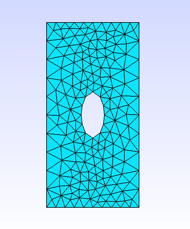
Example 1:
Rectangle r(_xmin=-3, _xmax=3, _ymin=-2, _ymax=2, _nnodes=Numbers(33,22), _domain_name="Omega_ext");
Ellipse e(_center=Point(0,0), _xlength=1, _ylength=0.5, _nnodes=11, _domain_name="Omega_int");
Mesh m1(r-e, _generator=gmsh);
Mesh m2(r+e, _generator=gmsh);
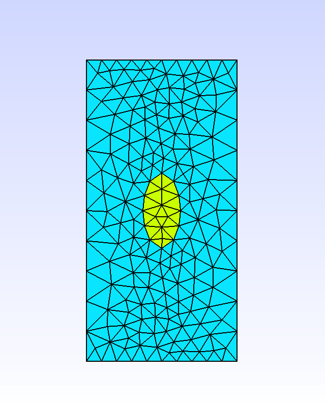
This generates for m1 a triangular mesh with only one surfacic domain “Omega_ext”. For m2, this generates a triangular mesh of the rectangle with 3 surfacic domains:
“Omega_ext” will be the domain of the difference between the rectangle and the ellipse (the same as in
m1)“Omega_int” will be the domain inside the ellipse
“Omega” will be the union of “Omega_ext” and “Omega_int”
Fig. 83 Gmsh view of m1 and m2. Domain “Omega_ext” is in cyan, domain “Omega_int” is in yellow.#
Exemple 2:
Ellipsoid ed1(_center=Point(0.,0.,0.), _v1=Point(3.,0.,0.), _v2=Point(0.,2.,0.), _v3=Point(0.,0.,1.),
              _nnodes=16);
Parallelepiped pa1(_v1=Point(-0.5,-0.5,-0.5), _v2=Point(0.5,-0.5,-0.5), _v4=Point(-0.5,0.5,-0.5),
                   _v5=Point(-0.5,-0.5,0.5), _nnodes=3);
Mesh mesh3dP1Composite(ed1-pa1,_tetrahedron,1,_gmsh);
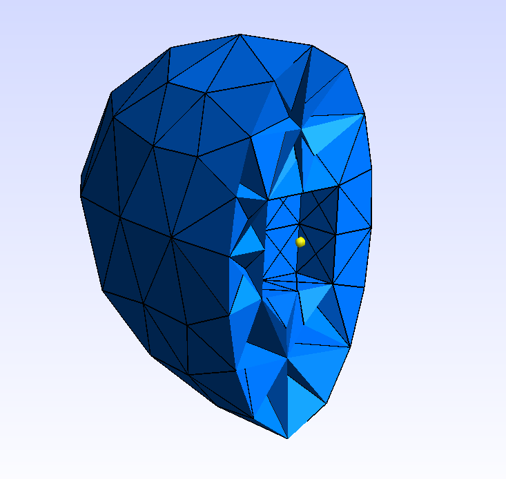
It shows how it works in 3D with a parallelepiped hole inside an ellipsoid.
Fig. 84 Gmsh views of a 3d composite geometry (ellipsoid - parallelepiped).#
Example 3:
Point a(-1.5,-4.), b(1.5,-4.), c(2.,-3.5), d(2.,3.5);
Point e(1.5,4.), f(-1.5,4.), g(-2.,3.5), h(-2.,-3.5);
Segment s1(_v1=a, _v2=b, _nnodes=21, _domain_name="AB");
CircArc c1(_center=Point(3.5,0.5), _v1=b, _v2=c, _nnodes=5, _domain_name="BC");
Segment s2(_v1=c, _v2=d, _nnodes=11, _domain_name="CD");
CircArc c2(_center=Point(3.5,1.5), _v1=d, _v2=e, _nnodes=5, _domain_name="DE");
Segment s3(_v1=e, _v2=f, _nnodes=21, _domain_name="EF");
CircArc c3(_center=Point(0.5,1.5), _v1=f, _v2=g, _nnodes=5,  _domain_name="FG");
Segment s4(_v1=g, _v2=h, _nnodes=11, _domain_name="GH");
CircArc c4(_center=Point(0.5,0.5), _v1=h, _v2=a, _nnodes=5, _domain_name="HA");
Mesh mesh2dP1Loop(surfaceFrom(s1+c1+s2+c2+s3+c3+s4+c4), _generator=gmsh);
This generates a triangular mesh of a rounded rectangle defined from its boundaries. Eachh component of the boundary will be a domain: “AB”, “BC”, “CD”, “dE”, “EF, “FG”, “GH”, and “HA”. There will be also a surfacic mesh names “Omega”.
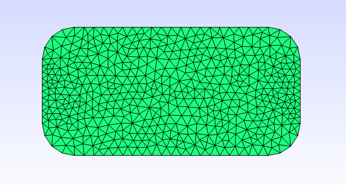
Fig. 85 Gmsh view of a rounded rectangle get from the surfaceFrom function.#
Exemple 4:
Strings sn("Gamma_1", "Gamma_2", "Gamma_3", "Gamma_4");
Ellipse e1(_center=Point(0.,0.), _v1=Point(4,0.), _v2=Point(0.,5.), _nnodes=12, _domain_name="Omega1", _side_names=sn);
sn[0]="Gamma_5"; sn[1]="Gamma_6"; sn[2]="Gamma_7"; sn[3]="Gamma_8";
Rectangle r1(_xmin=-2., _xmax=2., _ymin=-4., _ymax=4., _nnodes=11, _domain_name="Omega2", _side_names=sn);
sn[0]="Gamma_9"; sn[1]="Gamma_10"; sn[2]="Gamma_11"; sn[3]="Gamma_12";
Ellipse e2(_center=Point(1.,2.), _v1=Point(1.5,2.), _v2=Point(1.,3.), _nnodes=12, _side_names=sn);
sn[0]="Gamma_13"; sn[1]="Gamma_14"; sn[2]="Gamma_15"; sn[3]="Gamma_16";
Ellipse e3(_center=Point(0.,0.,0.), _v1=Point(0.5,0.,0.), _v2=Point(0.,1.,0.), _nnodes=12, _side_names=sn);
sn[0]="Gamma_17"; sn[1]="Gamma_18"; sn[2]="Gamma_19"; sn[3]="Gamma_20";
Rectangle r2(_xmin=5., _xmax=6., _ymin=0., _ymax=1., _nnodes=6, _domain_name="Omega3", _side_names=sn);
sn[0]="Gamma_21"; sn[1]="Gamma_22"; sn[2]="Gamma_23"; sn[3]="Gamma_24";
Disk d1(_center=Point(5.5,0.5,0.), _v1=Point(5.7,0.5,0.), _v2=Point(5.5,0.7,0.), _nnodes=12, _side_names=sn);
Mesh mesh2dP1Composite((e1+r1)-(e2+e3)+r2-d1,_triangle,1,_gmsh);
This generates a complex composite geometry whose some components are loop geometries and some holes created using the - operator. In most cases, XLiFE++ is able to detect properly
if a Geometry is inside another one or not.
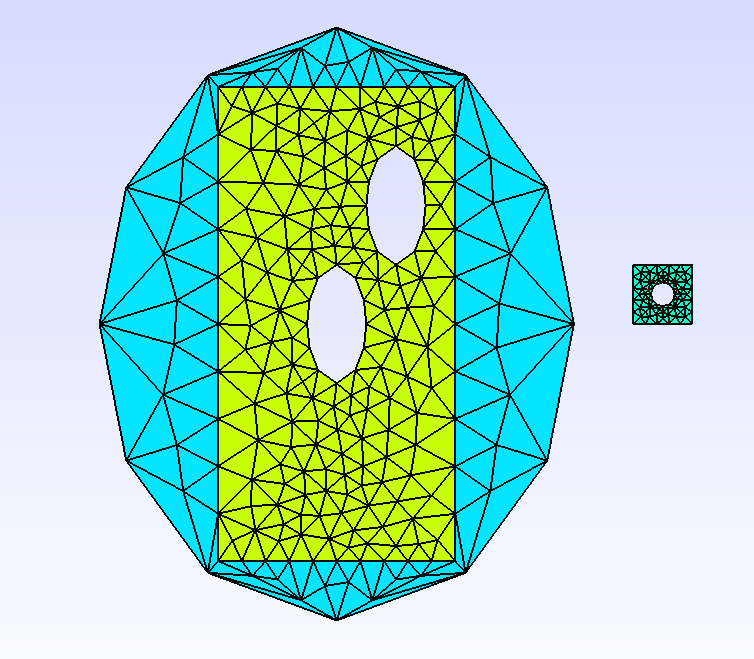
Fig. 86 Gmsh view of a complex geometry with merging and two holes.#
Example 5:
Ellipse e1(_center=Point(0.,0.), _v1=Point(4,0.), _v2=Point(0.,5.), _nnodes=12, _domain_name="Omega1");
Point a(-1.5,-4.); Point b(1.5,-4.); Point c(2.,-3.5); Point d(2.,3.5);
Point e(1.5,4.); Point f(-1.5,4.); Point g(-2.,3.5); Point h(-2.,-3.5);
Segment s1(_v1=a, _v2=b, _nnodes=21, _domain_name="AB");
CircArc c1(_center=Point(3.5,0.5), _v1=b, _v2=c, _nnodes=5, _domain_name="BC");
Segment s2(_v1=c, _v2=d, _nnodes=11, _domain_name="CD");
CircArc c2(_center=Point(3.5,1.5), _v1=d, _v2=e, _nnodes=5, _domain_name="DE");
Segment s3(_v1=e, _v2=f, _nnodes=21, _domain_name="EF");
CircArc c3(_center=Point(0.5,1.5), _v1=f, _v2=g, _nnodes=5, _domain_name="FG");
Segment s4(_v1=g, _v2=h, _nnodes=11, _domain_name="GH");
CircArc c4(_center=Point(0.5,0.5), _v1=h, _v2=a, _nnodes=5, _domain_name="HA");
Geometry sf1=surfaceFrom(s1+c1+s2+c2+s3+c3+s4+c4,"Omega2");
Ellipse e2(_center=Point(1.,2.), _v1=Point(1.5,2.), _v2=Point(1.,3.), _nnodes=12, _domain_name="Omega3");
Ellipse e3(_center=Point(0.,0.), _v1=Point(0.5,0.), _v2=Point(0.,1.), _nnodes=12, _domain_name="Omega4");
Rectangle r2(_xmin=5., _xmax=6., _ymin=0., _ymax=1., _nnodes=6, _domain_name="Omega5");
Segment s5(_v1=Point(5.3,0.5), _v2=Point(5.7,0.5), _nnodes=5);
CircArc c5(_center=Point(5.5,0.5), _v1=Point(5.7,0.5), _v2=Point (5.5,0.7), _nnodes=5);
CircArc c6(_center=Point(5.5,0.5), _v1=Point (5.5,0.7), _v2=Point(5.3,0.5), _nnodes=5);
Geometry sf2=surfaceFrom(s5+c5+c6,"Omega6");
Mesh mesh2dP1Composite3(e1+(sf1+(+(e2+e3))+r2+sf2, _generator=gmsh);
This generates a complex composite geometry whose some components are again loop geometries but holes have been replaced by mesh domains using the + operator.
If XLiFE++ warns that an inclusion has not been well detected, it is possible to force inclusion by using the unary + operator.
This is what is done to tell that the composite geometry e2+e3 is inside sf1.
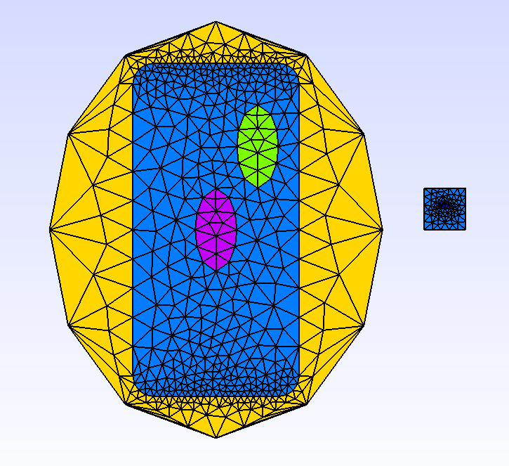
Fig. 87 gmsh view of mesh2dP1Composite3#
Example 6:
Mesh m(Rectangle(_xmin=0., _xmax=4., _ymin=0., _ymax=2., _nnodes=11),
       _generator=gmsh, _pattern=structured);
The gmsh generator also allows generating structured meshes, next to the internal structured generator. To say so, you have an additional key, _pattern,
whose default value is unstructured, but which can be used with structured.
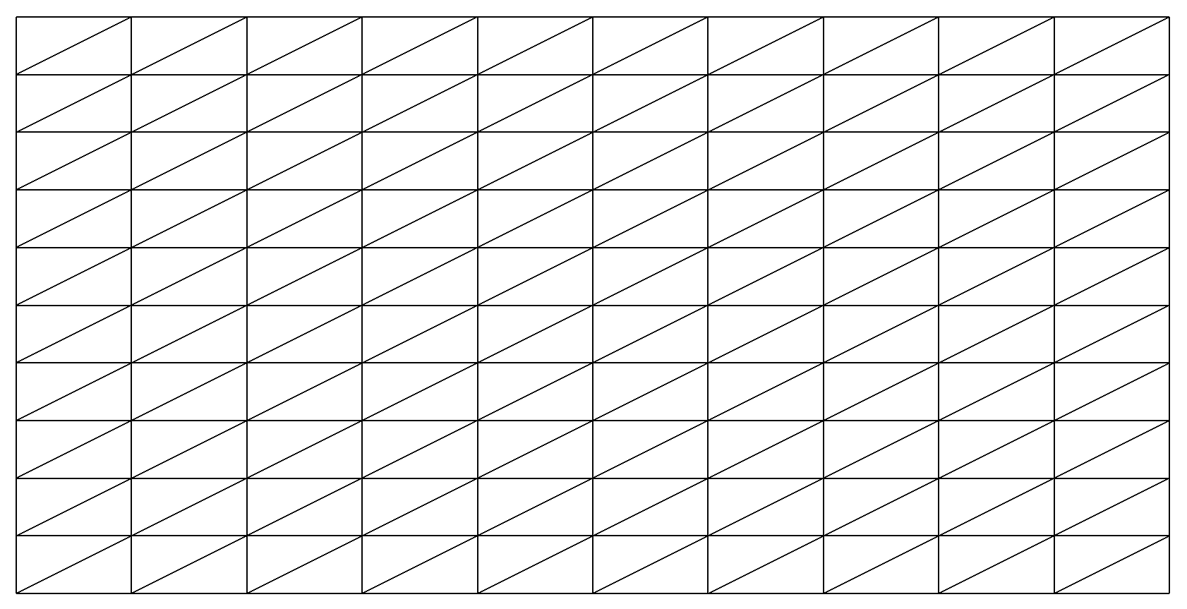
Fig. 88 View of structured mesh built using gmsh#
Note
By default, Gmsh produces meshes made of first order elements. By using the additional key _order, meshes with element of order from 1 to 5 can be generated; XLiFE++ being able to deal with.
Note
Gmsh is able to deal with cracks. To take advantage of this, XLiFE++ handles cracks in Geometry objects; see Cracking geometries for details.
GMSH-OC generator#
Open Cascade Technology (OCT) [1] is a third party open source library dedicated to 3D CAD data. It is a powerful library dealing with canonical geometries but providing complex geometrical operations (union, intersection, difference of geometries, fillet, chamfer, …). The standard geometry engine of XLiFE++ provides only union or difference in the case of one geometry included in another one (if detection is easy). So to go further, XLiFE++ provides an interface to OCT. Obviously, OCT must be installed and activated in XLiFE++ (cmake option).
Footnotes
Warning
OCT interface is still experimental. Use it with caution!
When OCT is enabled, it runs only if the user invokes an explicit OCT function. OCT objects (OCData class) are embedded in XLiFE++ geometry objects but are not allocated by default.
If an OCT function is invoked, OCT object will be allocated on the fly.
The main interest of OCT interface is to mesh complex object, for instance the intersection of two spheres perforated by a cylinder:
Sphere S1(_center=Point(1.,0,0.), _radius=1, _hsteps=0.02, _domain_name="S", _side_names="Sigma");
Sphere S2=translate(S1, _direction={1.5,0.,0.}); // _side_names "Sigma_2"
RevCylinder C(_center1=Point(1,0.,0), _center2=Point(2.5,0.,0.), _radius=0.3,_hsteps=0.02, _domain_name="C", _side_names="Gamma");
Geometry G=(S1^S2)-C; // intersection of spheres minus cylinder
At this stage, the geometry G handles only a symbolic description and does not handle any OCData object. It can be not dealt with usual mesh tools of XLiFE++ addressing only the standard gmsh engine.
Now invoking the Mesh constructor with the mesh generator option gmshOC will produce the creation of OCT objects related to geometries involved (here spheres and cylinder)
and an OCT object related to the geometry G that will be exported to Gmsh in a particular way.
Mesh M(G, _shape=triangle, _generator=gmshOC);
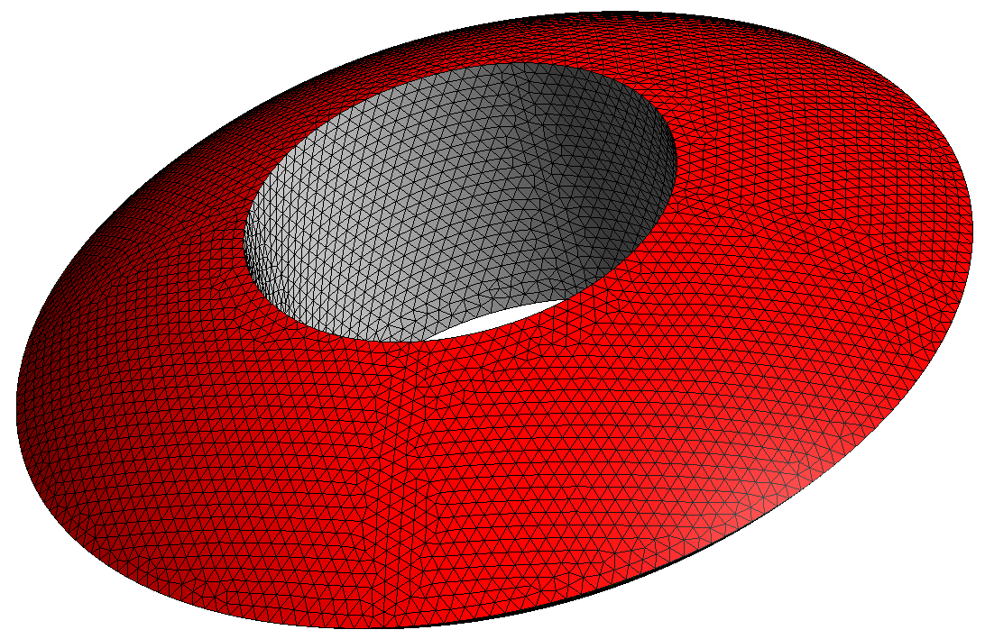
In this example, the name of domains created by Mesh are quite natural: “Sigma” and “Sigma_2” for the sphere boundaries and “Gamma” for the cylinder boundary. But in some more complex cases,
it can be not so intuitive to recover domain names, especially when new faces are created. There is a quite simple way to recover them. Indeed, when meshing with gmshOC generator,
3 files are created in the folder containing the executable file:
xlifepp.brep containing the brep export of the OCT object
xlifepp.geo, a gmsh script file containing the command to load the brep file and some additional commands related to mesh discretization and domain names.
xlifepp.msh, the mesh file created by gmsh and loaded by XLiFE++ to create the
Meshobject.
Loading the xlifepp.geo in gmsh and configuring it to see curve/surface labels will allow you to identify easier domain names.
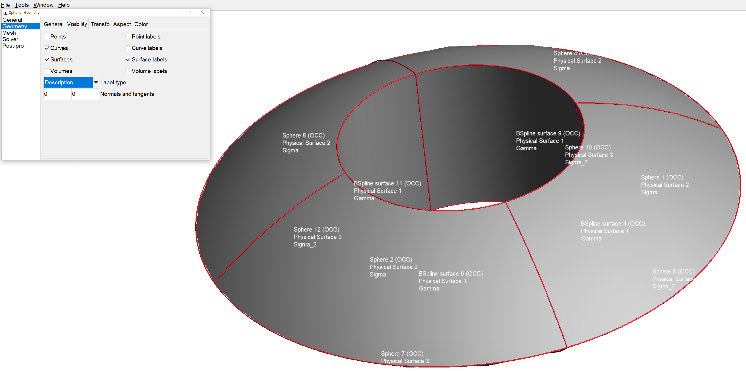
The next example shows how powerful is OCT and how XLiFE++ can manage complex geometries:
Cone co(_center1=Point(0.,0.,0.), _v1=Point(1.,0.,0.), _v2=Point(0.,1.,0.), _apex=Point(0.,0.,1),
        _hsteps=0.3,_side_names="gamma");
Cylinder cy(_center1=Point(0.,0.,0.), _v1=Point(0.7,0.,0.), _v2=Point(0.,0.7,0.),
            _center2=Point(0.,0.,7.), _hsteps=1,_side_names="gamma");
Sphere sp(_center=Point(0.,0.,7.), _radius=1., _hsteps=0.3,_side_names="gamma");
Geometry ant=cy+co+sp;
Real R=30., aR=0.999*R, d=0.2;
Sphere spcor(_center=Point(0.,0.,0.), _radius=R, _hsteps=2, _side_names="sigma");
Geometry cor=toComposite(spcor);
for (Number i=0;i<8;i++)
  for (Number j=0;j<7;j++)
  {
    Real ir = i+d*(2*std::rand() * (1.0 / RAND_MAX)-1),
         jr = j+d*(2*std::rand() * (1.0 / RAND_MAX)-1);
    Real t=pi_*(ir/4-1), p=pi_/8*(jr-3);
    Transformation tf = Translation(aR*cos(t)*cos(p), aR*sin(t)*cos(p), aR*sin(p))
                      * Rotation3d(Point(0,0,0), Point(0,0,1), t);
    tf *= Rotation3d(Point(0,0,0), Point(0,1,0), pi_/2-p);
    cor+=transform(ant, tf);
  }
Mesh M(cor, _shape=triangle, _generator=gmshOC);
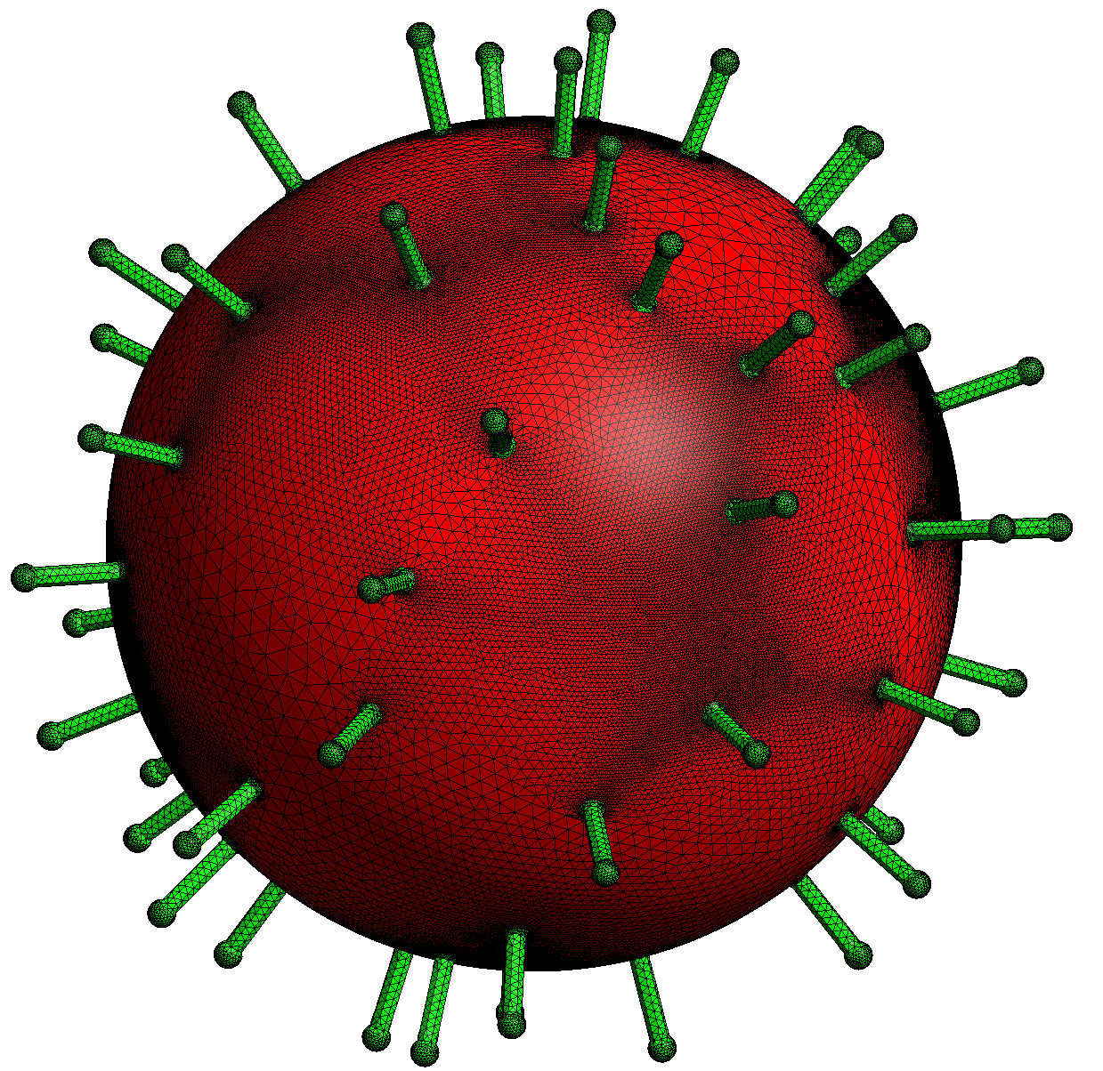
Main user’s functions#
void printOCInfo(CoutStream&) const;  // print info related to OC shapes to CoutStream
void printOCInfo(std::ostream&) const;// print info related to OC shapes to ostream
// build geometry from brep file
void loadFromBrep(const String& file, const Strings& domNames = Strings(),
                  const Strings& sideNames = Strings(), const Reals& hsteps = Reals());
// set name to some OC shapes given by a type and some num/id (0 means all shapes of OCShapeTYpe)
void setOCName(OCShapeType oct, const std::vector<Number>& nums, const String& na);
void setOCName(OCShapeType oct, Number num, const String& na);
// set hstep (>0) to OC vertices given by its num/id (0 means all vertices)
void setOCHstep(const std::vector<Number>& nums, Real hstep);
void setOCHstep(Number num, Real hstep);
// set nnode (>1) to some OC edges given by some num/id
void setOCNnode(Number num, Number nnode);
void setOCNnode(const std::vector<Number>& nums, Number nnode);
Available geometrical operations#
operation |
with OC extension |
standard geometry engine |
|---|---|---|
+ |
merge geometries (fusion) |
union of disjoint or included geometries |
- |
difference of geometries (cut) |
make a hole (included geometries) |
^ |
intersection of geometries (common) |
not available |
% |
not managed |
force inclusion |
Importing brep files#
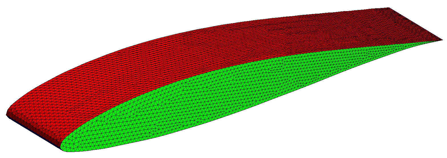
OCT extension provides a new interesting feature : loading a BREP file in a Geometry object and mesh it using the gmshOC generator:
Geometry naca("NACA63-412.brep");
naca.setOCName(_solid, 1, "naca");
naca.setOCName(_face, 1, "extrados"); //extrados face
naca.setOCName(_face, 2, "intrados"); //intrados face
naca.setOCName(_face, Numbers(3,4), "lateral"); //lateral faces
naca.setOCHstep(Numbers(1,3), 0.2);
naca.setOCHstep(Numbers(2,4), 0.1);
Mesh(naca, _generator=gmshOC);
In this example, after viewing in gmsh the “NACA63-412.brep” file and identify numbers of elementary objects (solid, face, point), some particular functions (setOCName, setOCHstep, setOCNnode) allow controlling names and mesh size parameters.
Mesh from parametrization#
To get more accurate meshes, XLiFE++ proposes (experimental) a meshing tool based on the parametrization of the geometry:
first, construct a mesh of the parametrization support
then, copy this mesh as the mesh of the geometry
finally, transform the points using the parametrization
In order to construct such mesh, use the generic Mesh constructor with the parameter _generator = _fromParametrization and _pattern with a value corresponding to an usual mesh generator
(_structured, _subdiv, _gmsh). When _pattern is not specified, the _structured generator is selected. Other parameters : _shape, _nnodes, _hsteps, _domainName, _sideNames may be used as usual.
For 1D canonical geometries, the parametrization support is the segment \([0,1]\) and for 2D canonical geometries is generally, the unit square \([0,1]\times[0,1]\). Up to now, 3D canonical geometry have no default parametrization, so it must be given explicitely by the user. Besides, some parametrizations may be degenerated (for instance, polar coordinates of a disk) and the previous process may fail (degenerated mesh). As a consequence, use this tool carefully.
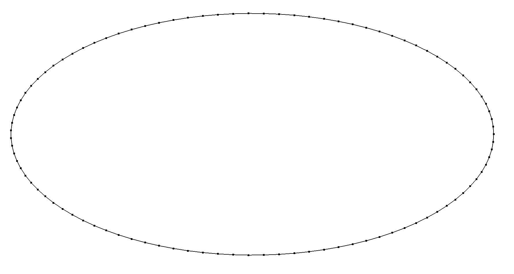
As a first example, consider the following mesh of a parametrized arc (ellipse):
Parametrization pe(0,2*pi_,2*cos(x_1),sin(x_1),Parameters(),"2cos(t),sin(t)");
ParametrizedArc parc(_parametrization = pe,_hsteps =0.01 ,_domain_name="Gamma");
Mesh mparc(parc, _shape=_segment, _order=1, _generator=_fromParametrization);
Now, consider the unit disk with its default parametrization (polar coordinates):
Disk d1(_center=Point(0.,0.),_radius=1, _nnodes=20);
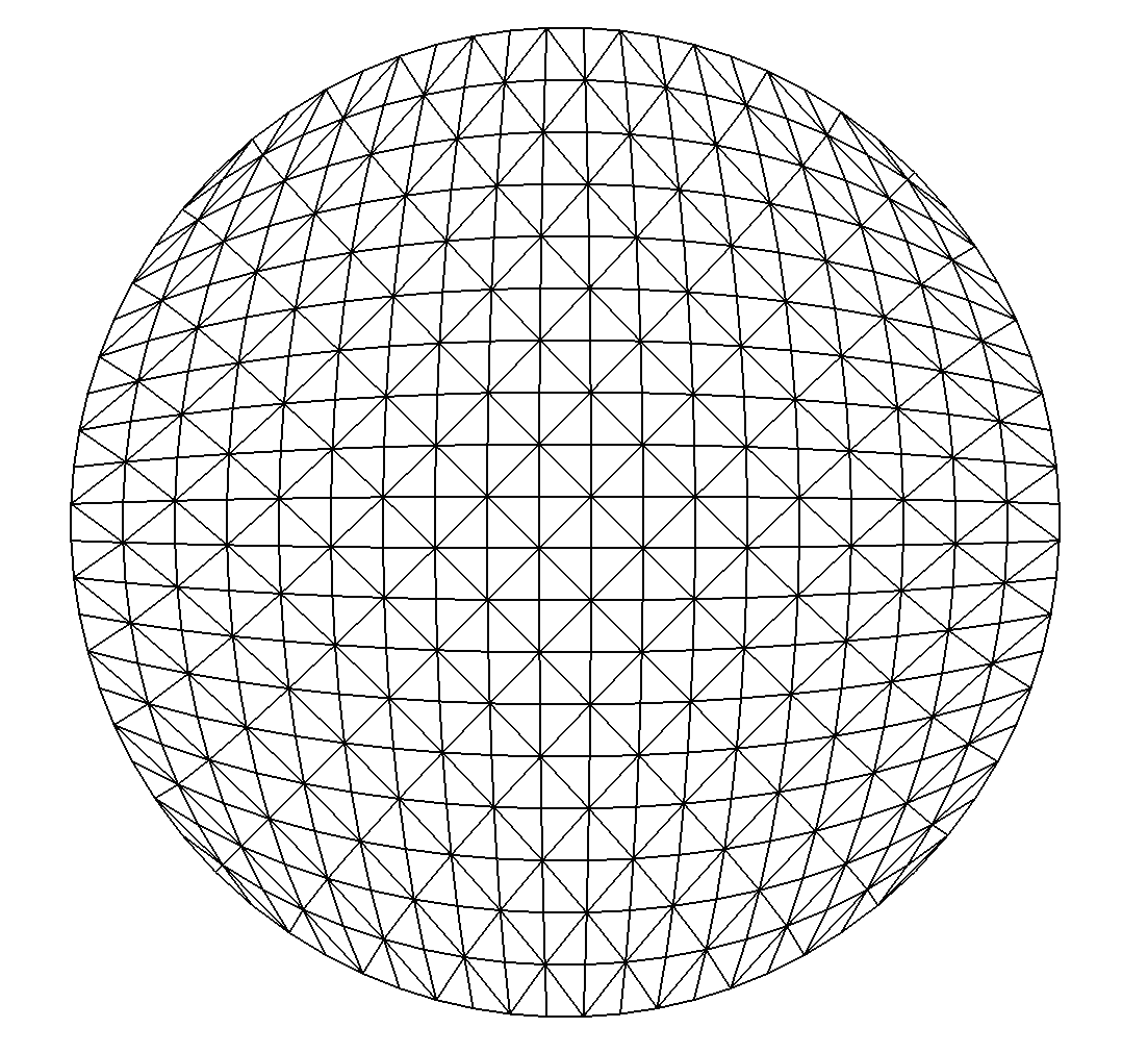
Mesh md1(d1, _shape=_triangle, _order=1, _generator=_fromParametrization);
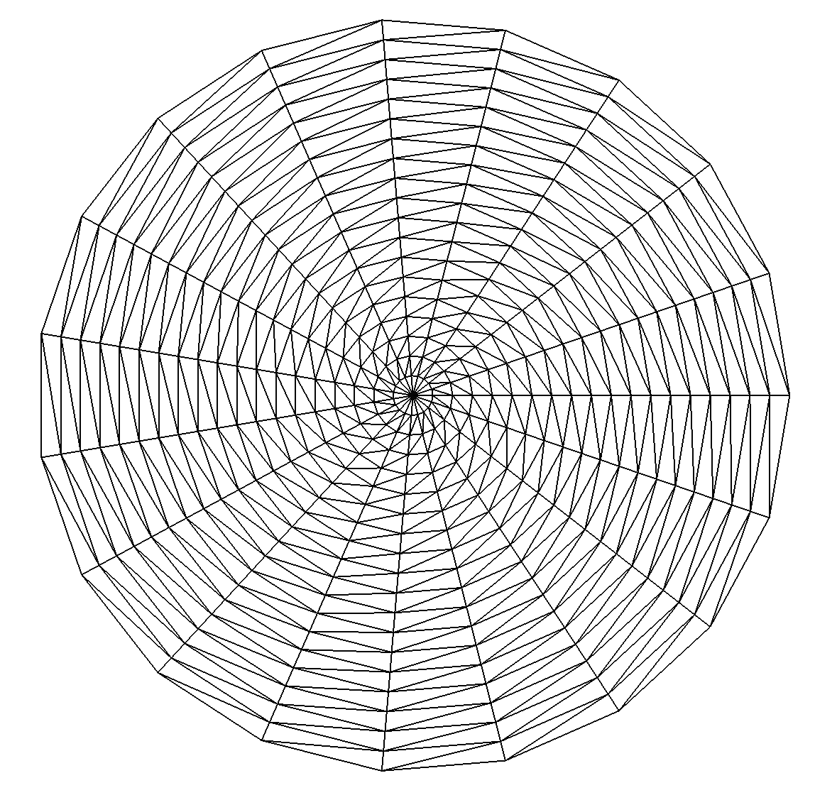
Note that the mesh is degenerated at the center of the disk!
Using an other parametrization (elliptical grid mapping):
a more satisfactory result can be obtained:
Vector<Real> ellPar(const Point& uv, Parameters& pars, DiffOpType d=_id)
{
  Real eps=1E-8, R=1+eps;
  Vector<Real> xy(2);
  Real u=2*uv[0]-1, v=2*uv[1]-1, u2=u*u, v2=v*v,
       ru=sqrt(1-0.5*u2), rv=sqrt(1-0.5*v2);
  xy[0]=u*rv*R; xy[1]=v*ru*R;
  return xy;
}

Vector<Real> invEllPar(const Point& xy, Parameters& pars, DiffOpType d=_id)
{
  Real eps=1E-8, R=1+eps, R2=R*R;
  Vector<Real> uv(2);
  Real x=xy[0], y=xy[1], x2=x*x, y2=y*y, r=2*sqrt(2);
  uv[0]=0.5*(1+0.5*sqrt(2+(x2-y2)/R2+r*x/R)-0.5*sqrt(2+(x2-y2)/R2-r*x/R));
  uv[1]=0.5*(1+0.5*sqrt(2+(y2-x2)/R2+r*y/R)-0.5*sqrt(2+(y2-x2)/R2-r*y/R));
  return uv;
}
...
Parameters pars;
Parametrization par(0, 1, 0, 1, ellPar, invEllPar, pars);
d1.setParametrization(par); // change disk parametrization
Mesh md1b(d1, _shape=_triangle, _order=1, _generator=_fromParametrization);
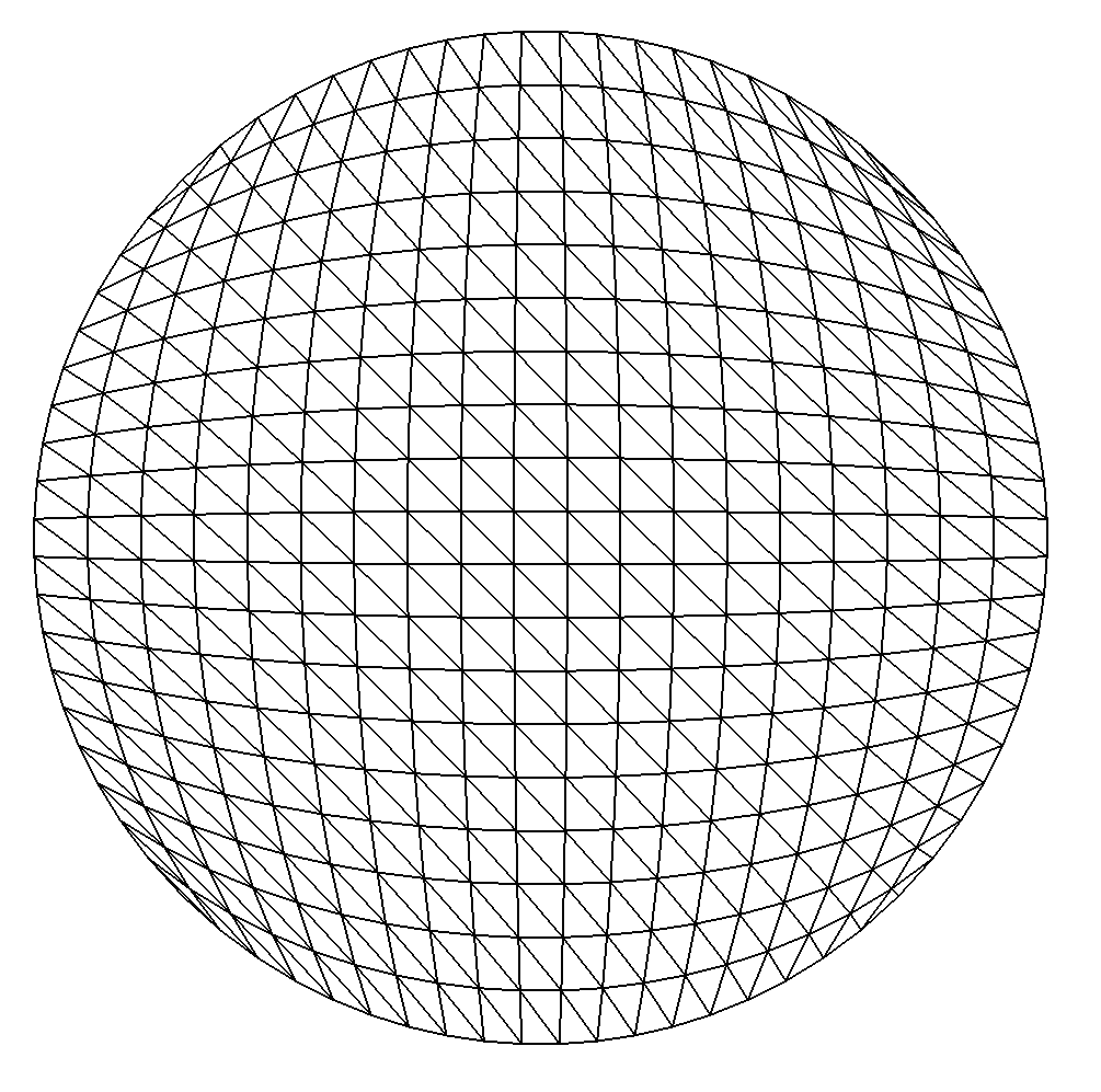
This parametrization degenerates on the boundary at angle \(\frac{\pi}{4}+k\frac{\pi}{2}\), it is the reason why the mesh is of lower quality in these areas.
The _structured generator has been used to mesh the geometry support (default when _pattern not given) with a left splitting of rectangles
(default when the _split_direction is not given). Using the alternate splitting:
Mesh md1b(d1, _shape=_triangle, _order=1, _generator=fromParametrization,
              _pattern=structured, _split_direction=alternate);
the following mesh is produced:
