


Finite elements#
A finite element in the physical space (Element object) is essentially defined by:
its geometric data, namely the geometric mesh element (
GeomElementobject, see Geometric element for more details)its basis functions in the physical space
Practically, it is built from the same data on the associated reference element (RefElement object). This is the purpose of the finiteElements library.
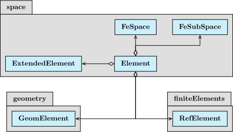
Fig. 126 Element class

Fig. 127 Element class
Available finite elements#
A finite element can be defined by 4 parameters, in Space constructor or in interpolation external function:
its type, set by the key
_FE_type. Possible values areLagrange,Hermite,CrouzeixRaviart,Nedelec,RaviartThomas,NedelecEdge,NedelecFace,Morley,Argyris;its optional variant, set by the key
_FE_subtype. Possible values arestandard,GaussLobattoPoints,firstFamily,secondFamilyaccording to the previous type;its interpolation order, set by the key
_order;and the Sobolev space on which the finite element lives, set by the key
_Sobolev_type. Possible values areL2,H1,Hdiv,Hcurl,H2,Hinf,Linf
Hint
You can also use the shortcut key _interpolation, that is more compact (Morley and Argyris excepted). Possible values are:
P0, P1, P2, P3, P4, P5, P6, P7, P8, P9, P10, P1BubbleP3,
CR
Q0, Q1, Q2, Q3, Q4, Q5, Q6, Q7, Q8, Q9, Q10

RT1, NF1_1 = RT1,
RT2, NF1_2 = RT2,
RT3, NF1_3 = RT3,
RT4, NF1_4 = RT4,
RT5, NF1_5 = RT5,
BDM1, NF2_1 = BDM1,
BDM2, NF2_2 = BDM2,
BDM3, NF2_3 = BDM3,
BDM4, NF2_4 = BDM4,
BDM5, NF2_5 = BDM5,

N1_1, NE1_1 = N1_1,
N1_2, NE1_2 = N1_2,
N1_3, NE1_3 = N1_3,
N1_4, NE1_4 = N1_4,
N1_5, NE1_5 = N1_5,
N2_1, NE2_1 = N2_1,
N2_2, NE2_2 = N2_2,
N2_3, NE2_3 = N2_3,
N2_4, NE2_4 = N2_4,
N2_5, NE2_5 = N2_5
Let’s now talk about the different finite elements that are implemented in XLiFE++.
Lagrange finite elements#
There are 2 variants of Lagrange finite elements: Standard Lagrange elements and Gauss-Lobatto Lagrange elements
Standard Lagrange elements#
They are defined on:
segment at any order (see
LagrangeStdSegmentfor more details)
|
Fig. 128 Segment P1
Fig. 129 Segment P1 |
Fig. 130 Segment P2
Fig. 131 Segment P2 |
|
Fig. 132 Segment P3
Fig. 133 Segment P3 |
Fig. 134 Segment P4
Fig. 135 Segment P4 |








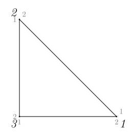
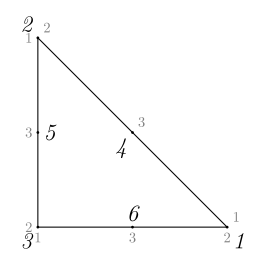
triangle at any order (see
LagrangeStdTrianglePkfor more details), with explicit formulae up to order 6 (managed by classLagrangeStdTriangle<_Pk>)
|
Fig. 136 Triangle P1
Fig. 137 Triangle P1 |
Fig. 138 Triangle P2
Fig. 139 Triangle P2 |
|
Fig. 140 Triangle P3
Fig. 141 Triangle P3 |
Fig. 142 Triangle P4
Fig. 143 Triangle P4 |
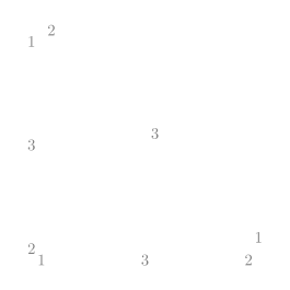
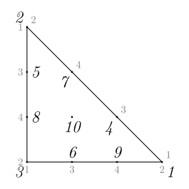
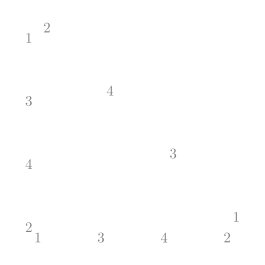
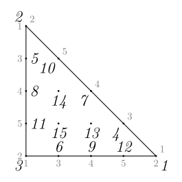
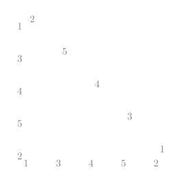
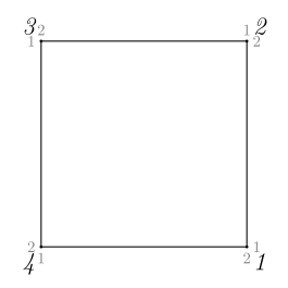
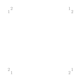
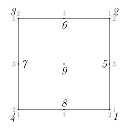
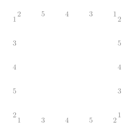
quadrangle at any order (see
LagrangeStdQuadranglefor more details)
|
Fig. 144 Quadrangle Q1
Fig. 145 Quadrangle Q1 |
Fig. 146 Quadrangle Q2
Fig. 147 Quadrangle Q2 |
|
Fig. 148 Quadrangle Q3
Fig. 149 Quadrangle Q3 |
Fig. 150 Quadrangle Q4
Fig. 151 Quadrangle Q4 |
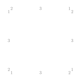
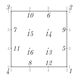
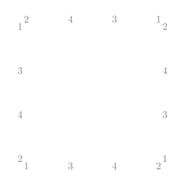
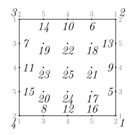
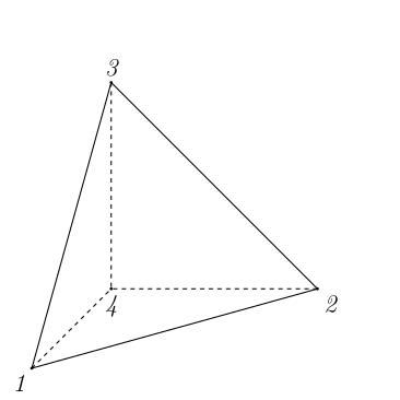
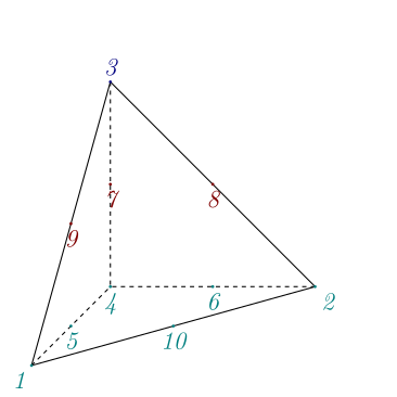
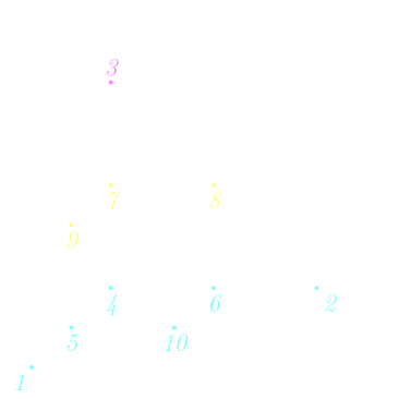
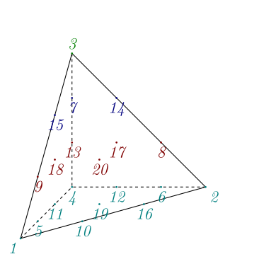
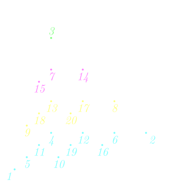
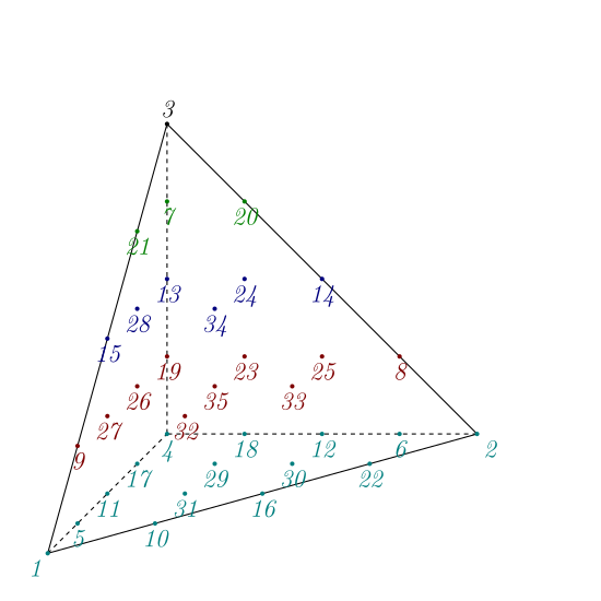
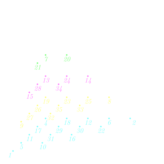
tetrahedron at any order (see
LagrangeStdTetrahedronPkfor more details), with explicit formulae up to order 6 (managed byLagrangeStdTetrahedron<_Pk>for more details)
|
Fig. 152 Tetrahedron P1
Fig. 153 Tetrahedron P1 |
Fig. 154 Tetrahedron P2
Fig. 155 Tetrahedron P2 |
|
Fig. 156 Tetrahedron P3
Fig. 157 Tetrahedron P3 |
Fig. 158 Tetrahedron P4
Fig. 159 Tetrahedron P4 |

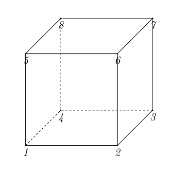
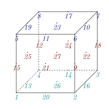
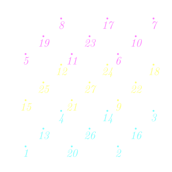
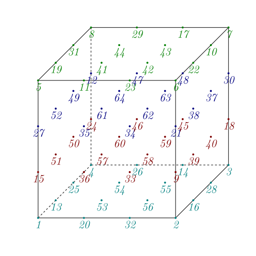
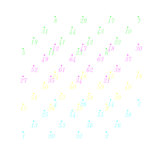
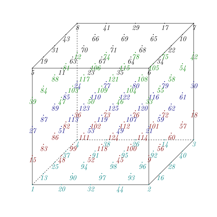
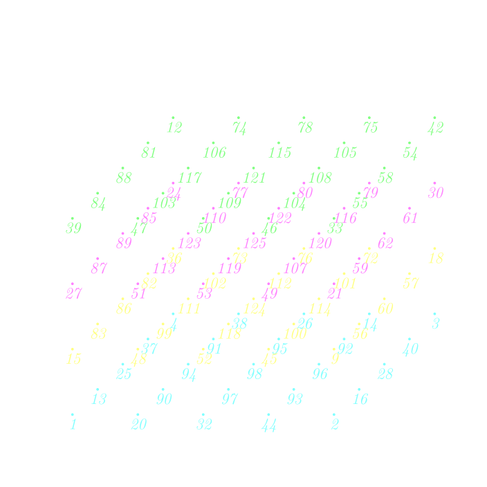
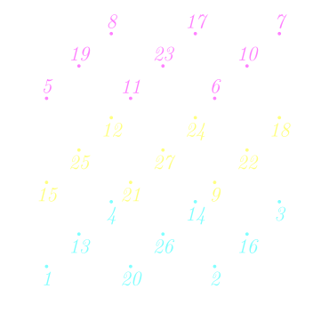
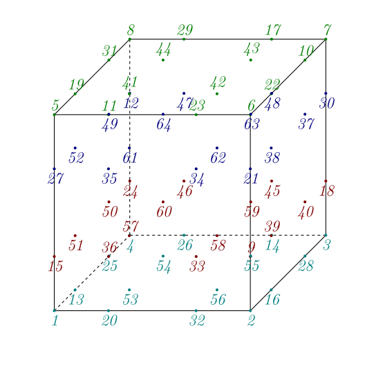
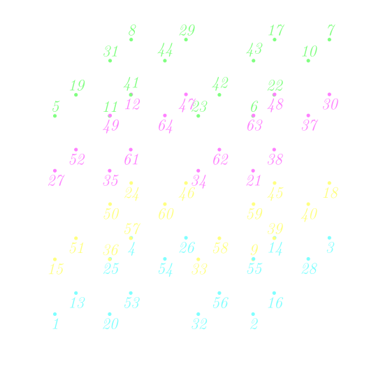
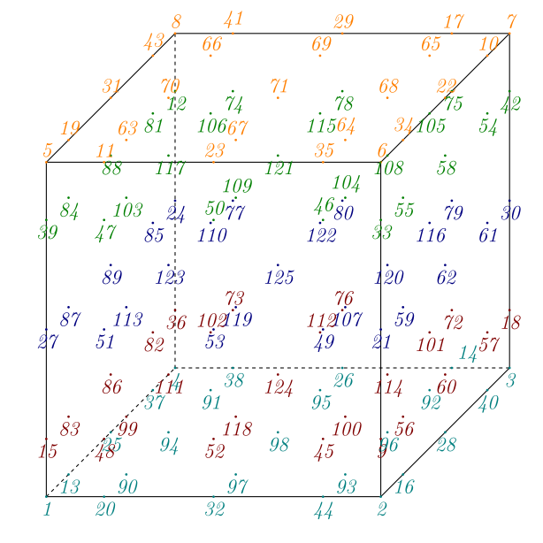
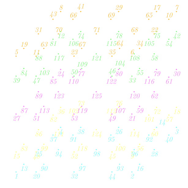
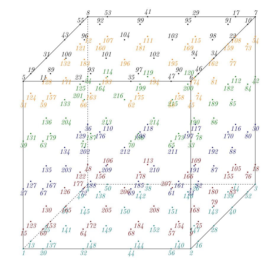
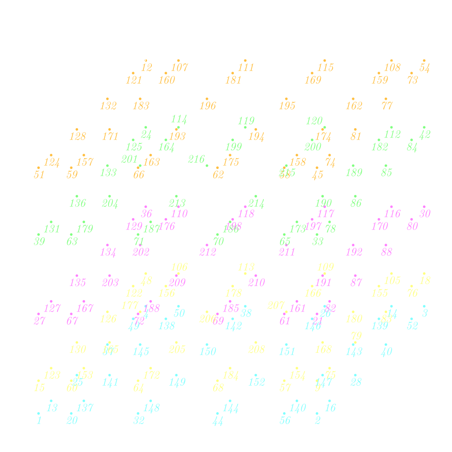
hexahedron at any order (see
LagrangeStdHexahedronfor more details)
|
Fig. 160 Hexahedron Q1
Fig. 161 Hexahedron Q1 |
Fig. 162 Hexahedron Q2
Fig. 163 Hexahedron Q2 |
|
Fig. 164 Hexahedron Q3
Fig. 165 Hexahedron Q3 |
Fig. 166 Hexahedron Q4
Fig. 167 Hexahedron Q4 |

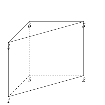
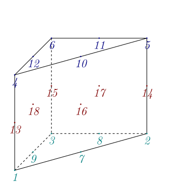
prism up to order 2 (see
LagrangeStdPrism<_Pk>for more details)
|
Fig. 168 Prism O1
Fig. 169 Prism O1 |
Fig. 170 Prism O2
Fig. 171 Prism O2 |

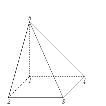
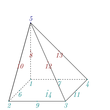
pyramid up to order 2 (see
LagrangeStdPyramid<_Pk>for more details)
|
Fig. 172 Pyramid O1
Fig. 173 Pyramid O1 |
Fig. 174 Pyramid O2
Fig. 175 Pyramid O2 |

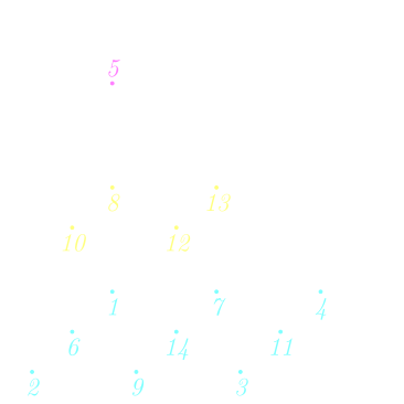
Gauss Lobatto Lagrange elements#
They are defined on:
segment at any order (see
LagrangeGLSegmentfor more details)
|
Fig. 176 Segment P2 Gauss-Lobatto
Fig. 177 Segment P2 Gauss-Lobatto |
Fig. 178 Segment P3 Gauss-Lobatto
Fig. 179 Segment P3 Gauss-Lobatto |
|
Fig. 180 Segment P4 Gauss-Lobatto
Fig. 181 Segment P4 Gauss-Lobatto |
Fig. 182 Segment P5 Gauss-Lobatto
Fig. 183 Segment P5 Gauss-Lobatto |






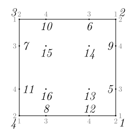
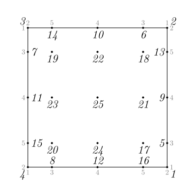
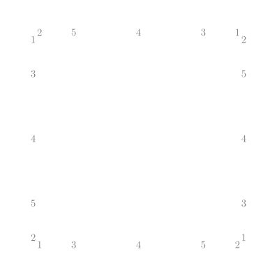
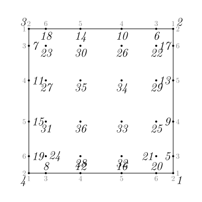
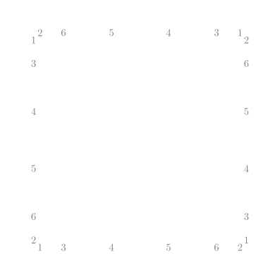
quadrangle at any order (see
LagrangeGLQuadranglefor more details)
|
Fig. 184 Quadrangle Q2 Gauss-Lobatto
Fig. 185 Quadrangle Q2 Gauss-Lobatto |
Fig. 186 Quadrangle Q3 Gauss-Lobatto
Fig. 187 Quadrangle Q3 Gauss-Lobatto |
|
Fig. 188 Quadrangle Q4 Gauss-Lobatto
Fig. 189 Quadrangle Q4 Gauss-Lobatto |
Fig. 190 Quadrangle Q5 Gauss-Lobatto
Fig. 191 Quadrangle Q5 Gauss-Lobatto |
hexahedron at any order (see
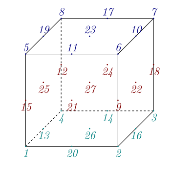
LagrangeGLHexahedronfor more details)
|
Fig. 192 Hexahedron Q2 Gauss-Lobatto
Fig. 193 Hexahedron Q2 Gauss-Lobatto |
Fig. 194 Hexahedron Q3 Gauss-Lobatto
Fig. 195 Hexahedron Q3 Gauss-Lobatto |
|
Fig. 196 Hexahedron Q4 Gauss-Lobatto
Fig. 197 Hexahedron Q4 Gauss-Lobatto |
Fig. 198 Hexahedron Q5 Gauss-Lobatto
Fig. 199 Hexahedron Q5 Gauss-Lobatto |
Hermite finite elements#
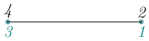
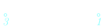
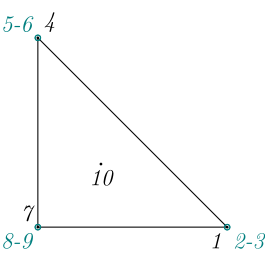
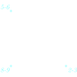
They are defined on segment (see HermiteStdSegment<_Pk> for more details) and triangle (see HermiteStdTriangle<_Pk> for more details):
|
Fig. 200 Segment Hermite
Fig. 201 Segment Hermite |
Fig. 202 Triangle Hermite
Fig. 203 Triangle Hermite |
Crouzeix-Raviart finite elements#
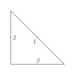
They are defined on triangle (see CrouzeixRaviartStdTriangleP1 for more details) and tetrahedron (see CrouzeixRaviartStdTetrahedronP1 for more details):
|
Fig. 204 Triangle Crouzeix-Raviart
Fig. 205 Triangle Crouzeix-Raviart |
Fig. 206 Tetrahedron Crouzeix-Raviart
Fig. 207 Tetrahedron Crouzeix-Raviart |

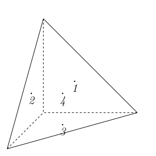

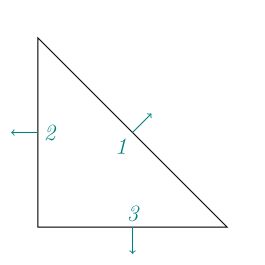
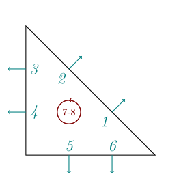
Raviart-Thomas / Nedelec Face firstFamily finite elements#
They are defined on:
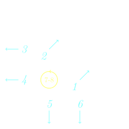
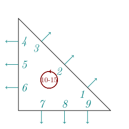
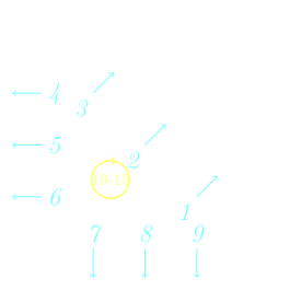
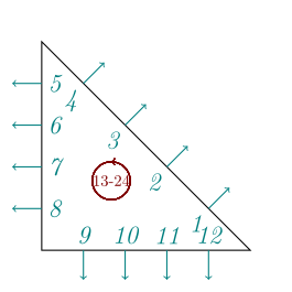
triangle (see
RaviartThomasStdTriangleP1andRaviartThomasStdTrianglePkfor more details)
|
Fig. 208 Triangle RT1
Fig. 209 Triangle RT1 |
Fig. 210 Triangle RT2
Fig. 211 Triangle RT2 |
|
Fig. 212 Triangle RT3
Fig. 213 Triangle RT3 |
Fig. 214 Triangle RT4
Fig. 215 Triangle RT4 |
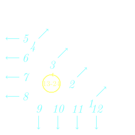
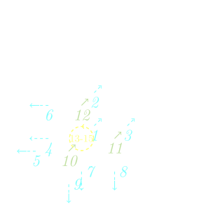
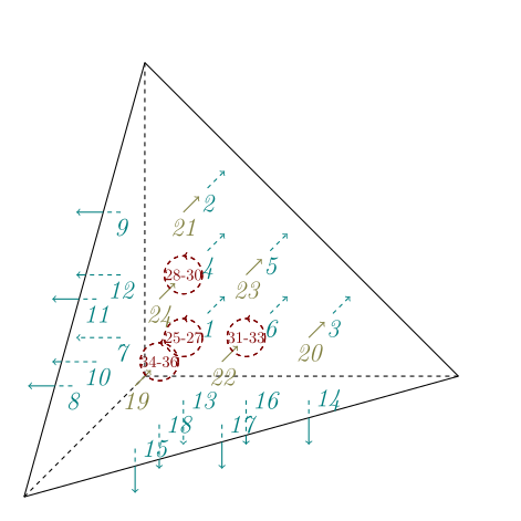
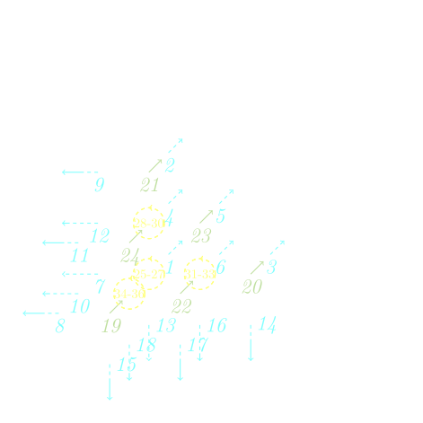
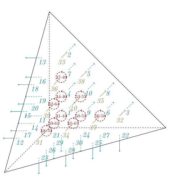
tetrahedron (see
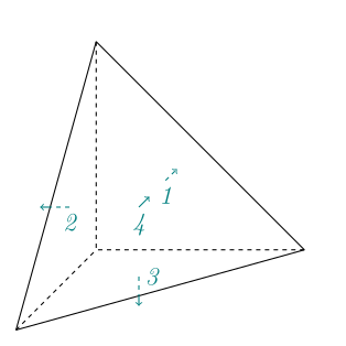
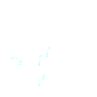
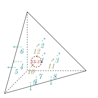
NedelecFaceFirstTetrahedronPkfor more details)
|
Fig. 216 Tetrahedron RT1
Fig. 217 Tetrahedron RT1 |
Fig. 218 Tetrahedron RT2
Fig. 219 Tetrahedron RT2 |
|
Fig. 220 Tetrahedron RT3
Fig. 221 Tetrahedron RT3 |
Fig. 222 Tetrahedron RT4
Fig. 223 Tetrahedron RT4 |
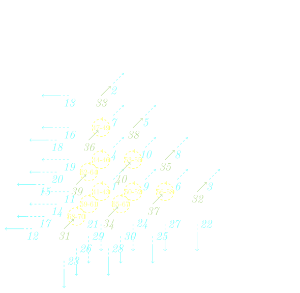
Nedelec / Nedelec Edge first family finite elements#
They are defined on:
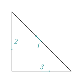
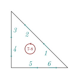
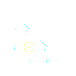
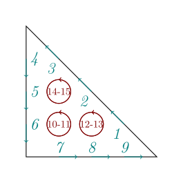
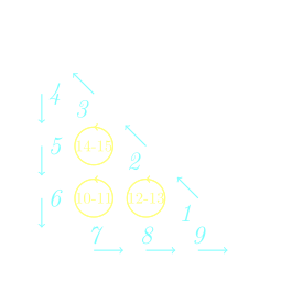
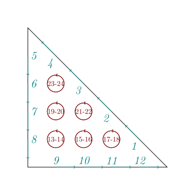
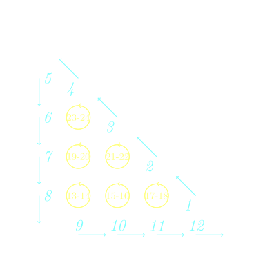
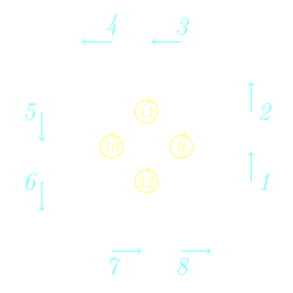
triangle, up to order 5, (see
NedelecFirstTriangleP1andNedelecFirstTrianglePkfor more details)
|
Fig. 224 Triangle NE1_1
Fig. 225 Triangle NE1_1 |
Fig. 226 Triangle NE1_2
Fig. 227 Triangle NE1_2 |
|
Fig. 228 Triangle NE1_3
Fig. 229 Triangle NE1_3 |
Fig. 230 Triangle NE1_4
Fig. 231 Triangle NE1_4 |
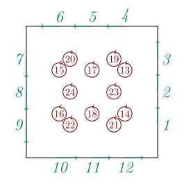
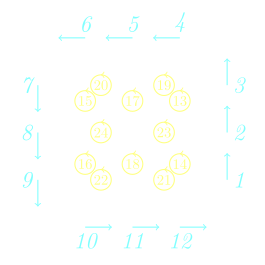
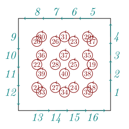
quadrangle, up to order 5, (see
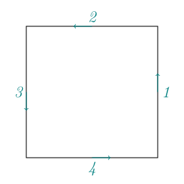
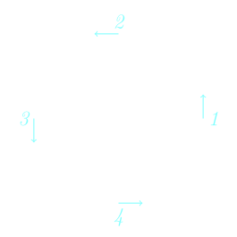
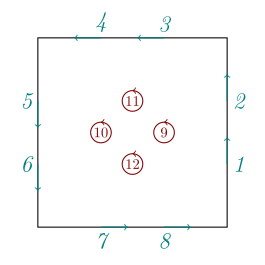
NedelecEdgeFirstQuadranglePkfor more details)
|
Fig. 232 Quadrangle NE1_1
Fig. 233 Quadrangle NE1_1 |
Fig. 234 Quadrangle NE1_2
Fig. 235 Quadrangle NE1_2 |
|
Fig. 236 Quadrangle NE1_3
Fig. 237 Quadrangle NE1_3 |
Fig. 238 Quadrangle NE1_4
Fig. 239 Quadrangle NE1_4 |
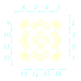
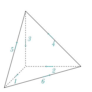
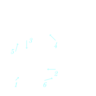
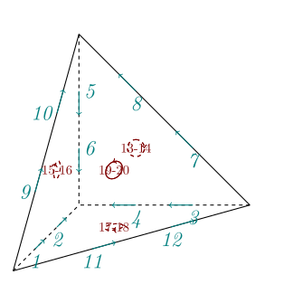
tetrahedron, up to order 5, (see
NedelecEdgeFirstTetrahedronPkfor more details)
|
Fig. 240 Tetrahedron NE1_1
Fig. 241 Tetrahedron NE1_1 |
Fig. 242 Tetrahedron NE1_2
Fig. 243 Tetrahedron NE1_2 |
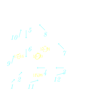
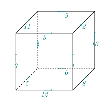
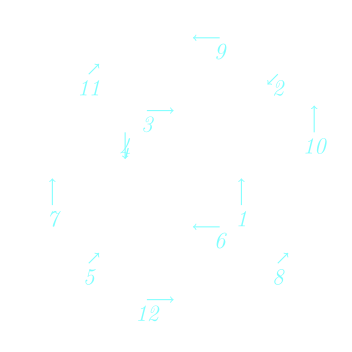
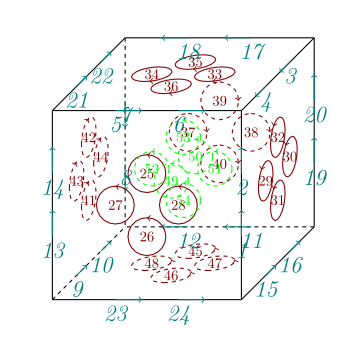
hexahedron, up to order 5, (see
NedelecEdgeFirstHexahedronPkfor more details)
|
Fig. 244 Hexahedron NE1_1
Fig. 245 Hexahedron NE1_1 |
Fig. 246 Hexahedron NE1_2
Fig. 247 Hexahedron NE1_2 |
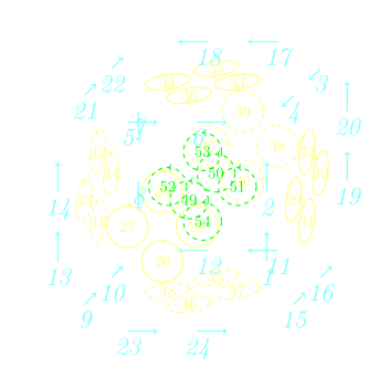
Hint
NedelecEdgeTetrahedron and NedelecFaceTetrahedron classes use a general process to build shape functions as polynomials related to moment DOFs. To match DOFs on shared edge or shared face, the ascending numbering of vertices is implicitly used even if it is not in fact. This method is particular touchy in case of face DOFs of Nedelec Edge element. Indeed, such DOFs depend on the choice of two tangent vectors, generally two edges of faces of the reference tetrahedron that are mapped to some edges of physical element in a non-trivial way. To ensure a correct matching of such DOFs on a shared face, a rotation has to be applied to shape values to guarantee that they correspond to the same tangent vectors. This is the role of the member function rotateDofs.
Note that if the element vertex numbering and face vertex numbering are ascending, rotateDofs does nothing. This trick is commonly used to overcome this difficulty but as XLiFE++ makes no assumption on geometry, this DOFs rotation is mandatory.
More details on edge/face elements are provided in a specific paper.
Morley finite elements#
They are defined on triangle (see MorleyTriangle for more details):
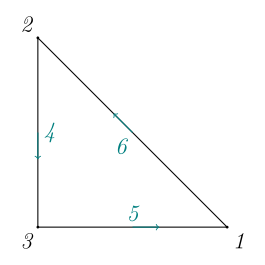
Fig. 248 Triangle Morley
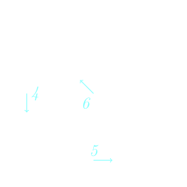
Fig. 249 Triangle Morley
Argyris finite elements#
They are defined on triangle (see ArgyrisTriangle for more details)
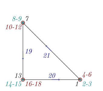
Fig. 250 Triangle Argyris
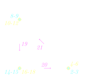
Fig. 251 Triangle Argyris
The RefElement class#
The base class RefElement handles the following data:
an
Interpolationobject carrying some general information on the finite element such that the finite element type and its conforming space,a
GeomRefElementobject describing the geometric support of the reference element,a vector of
RefDofto handle all the degrees of freedom (DOF) attached to the reference element,and additional stuff useful for the computation (for instance
ShapeValuesobject to store the values of shape functions).
All concrete finite element classes are organized into sub-libraries according to their geometric shape, under the following inheritance diagram:
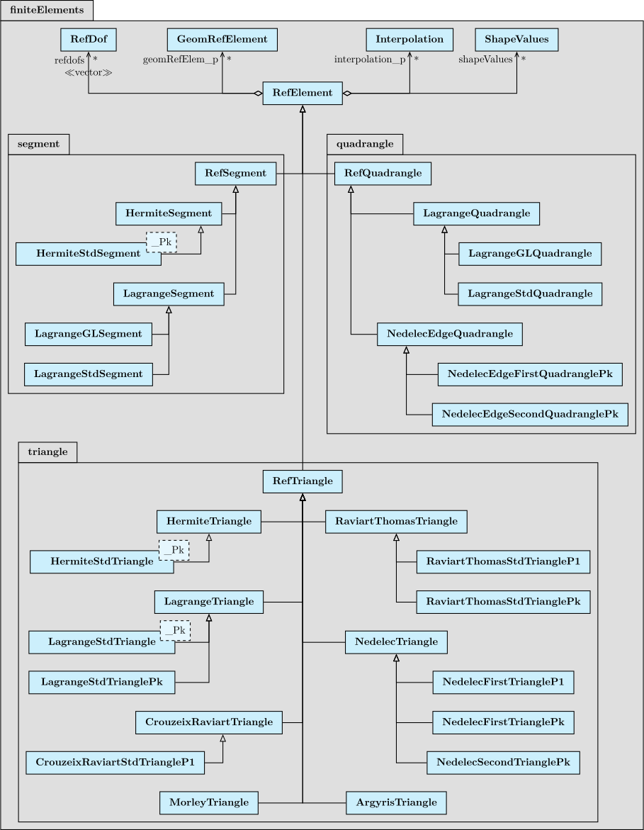
Fig. 252 RefElement class and 1d-2d childs
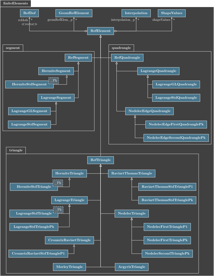
Fig. 253 RefElement class and 1d-2d childs
This hierarchy is the reason why RefElement is a complex class collecting a lot of information and providing many numbering functions such as the number of DOFs, the same number on vertices, on sides, on side of sides, …:
class RefElement
{
  public:
    GeomRefElement* geomRefElem_p;        // pointer to geometric reference element
    const Interpolation* interpolation_p; // interpolation parameters
    vector<RefDof*> refDofs;              // local reference Degrees of Freedom
    FEMapType mapType;                    // type of map applied to shape functions
    DofCompatibility DoFCompatibility;    // compatibility rule to applied to side DOFs
    Dimen dimShapeFunction;               // dimension of shape function
    Number maxDegree;                     // maximum degree of shape functions
    bool rotateDof;                       // if true, apply rotation to shape values
  protected:
    String name_;                // name (for documentation)
    Number nbDofs_;              // nb of Degrees Of Freedom
    Number nbPts_;               // nb of Points (for local coordinates of points)
    Number nbDofsOnVertices_;    // nb of sharable DOF on vertices (first DOF)
    Number nbDofsInSideOfSides_; // nb of sharable DOF on side of sides (edges)
    Number nbDofsInSides_;       // nb of sharable DOF on sides (faces or edges)
    Number nbInternalDofs_;      // nb of non-sharable DOF's
    vector<RefElement*> sideRefElems_;       // pointers to side reference elements
    vector<RefElement*> sideOfSideRefElems_; // pointers to side of side reference elements
  public:
    vector<vector<Number>> sideDofNumbers_;         // DOF numbers for each side
    vector<vector<Number>> sideOfSideDofNumbers_;   // DOF numbers for each side of side
    PolynomialsBasis Wk;                            // shape functions basis as polynomials
    vector<PolynomialsBasis> dWk;                   // derivatives of shape functions
    map<Quadrature*,vector<ShapeValues>> qshvs_;    // to store shape function values
    map<Quadrature*,vector<ShapeValues>> qshvs_aux; // to store shape function values
};
The FEMapType enumerates the types of affine mapping from reference element to any element. It depends on finite element type:
enum FEMapType {_standardMap, _contravariantPiolaMap, _covariantPiolaMap, _MorleyMap, _ArgyrisMap};
Most of the data are filled by inherited classes (true finite element class). Shape functions of high order element are boring to find. So, XLiFE++ provides tools to get them in a formal way,
using Polynomials class. The virtual function computeShapeFunctions computes them and the buildPolynomialTree function
builds a tree representation of the formal representation of shape functions, in order to make faster their computations.
This class drives the computation of shape function values, using the virtual member function:
void computeShapeValue(pt_iterator itp, ShapeValues& shv, bool withDer = true,
                                                     bool withwithDer2 = false);
The Interpolation class#
The purpose of the Interpolation class is to store data related to finite element
interpolation. It concerns only general description of an interpolation:
type of the finite element interpolation (Lagrange, Hermite, …),
subtype among standard, Gauss-Lobatto (only for Lagrange) and first or second family (only for Nedelec),
the “order” of the interpolation
the space conformity (one of L2, H1, Hdiv, Hcurl, H2).
For instance, a Lagrange standard P1 with H1 conforming is the classic P1 Lagrange interpolation but a Lagrange standard P1 with L2 conforming means a discontinuous interpolation (like Galerkin discontinuous approximation) where the vertices of an element are not shared.
For the moment, this class is only intended to support the following choices, that correspond to the _FE_type, the _FE_subtype and the _order keys used in Space construction:
type |
subtype |
order |
|---|---|---|
Lagrange |
standard, Gauss-Lobatto |
any order |
Hermite |
standard |
|
Morley |
standard |
order 2 |
Argyris |
standard |
order 5 |
Crouzeix-Raviart |
standard |
order 1 |
Raviart-Thomas |
standard |
any order |
Nedelec |
first or second family |
any order |
Nedelec face |
first or second family |
any order |
Nedelec edge |
first or second family |
any order |
Hint
Nedelec face and Nedelec edge are specific to 3d. Nedelec face corresponds to the 2d Raviart-Thomas family and Nedelec edge corresponds to the 2d Nedelec family.
Hint
The Interpolation class is intended to support a lot of finite element family, but all are not available. See child classes of RefElement class to know which families are actually available.
The class Interpolation has the following attributes:
class Interpolation
{
  public:
    const FEType type;        // interpolation type
    const FESubType subtype;  // interpolation subtype
    const Number numtype;     // additional number type (degree for Lagrange)
    SobolevType conformSpace; // conforming space
    String name;              // name of the interpolation type
    String subname;           // interpolation sub_name
    String shortname;         // short name (see build)
};
FEType, FESubType and SpaceType are enumerations defined in the
config.hpp file as follows:
enum SobolevType {L2=0, H1, Hdiv, Hcurl, Hrot=Hcurl, H2, Hinf};
enum FEType {Lagrange, Hermite, CrouzeixRaviart, Nedelec, RaviartThomas,
             NedelecFace, NedelecEdge, Morley, Argyris};
enum FESubType {standard=0, GaussLobattoPoints, firstFamily, secondFamily};
Interpolation objects may be constructed as follows:
Interpolation& intp=interpolation(Lagrange, standard, 2, H1); // using implicit constructor
The GeomRefElement class#
The GeomRefElement class carries geometric data of a reference element: type, dimension, number of vertices, sides and side of sides, measure, and coordinates of vertices.
Furthermore, to help to find geometric data on sides, it also carries type, vertex numbers of each side on the first hand, and vertex numbers and relative number to parent side of each side of side
on the second hand:
class GeomRefElement
{
  protected:
    ShapeType shapeType_;     //element shape
    const Dimen dim_;         //element dimension
    const Number nbVertices_, nbSides_, nbSideOfSides_; //number of vertices, ...
    const Real measure_;                       //length or area or volume
    vector<Real> centroid_;                    //coordinates of centroid
    vector<Real> vertices_;                    //coordinates of vertices
    vector<ShapeType> sideShapeTypes_;         //shape type of each side
    vector<vector<Number> > sideVertexNumbers_;
    vector<vector<Number> > sideOfSideVertexNumbers_;
    vector<vector<Number> > sideOfSideNumbers_;
};
This class proposes various functions to get geometric information and has has child classes :
GeomRefSegmentin 1d,GeomRefTriangleandGeomRefQuadranglein 2dGeomRefHexahedron,GeomRefTetrahedron,GeomRefPrismandGeomRefPyramidin 3d.
that propose specific numbering functions.
The RefDof class#
The RefDof class handles the representation of a generalized degree of freedom in a reference element. It manages:
A support that can be a point, a side, a side of side or the whole element. When it is a point, its coordinates are available.
A dimension, that means the number of components of shape functions of the DOF.
Projections data (type and direction) when the DOF is a projection DOF. The projection type is 0 for a general projection, 1 for a \(u.n\) DOF, 2 for a \(u\times n\) DOF.
Derivative data (order and direction) when the DOF is a derivative DOF. The order is 0 when the DOF is defined by an ‘integral’ over its support, or \(n\) for a Hermite DOF derivative of order \(n>0\) or a moment DOF of order \(n>0\).
A shareable property: a DOF is shareable when it is shared between adjacent elements according to space conformity. Such a DOF can be shared or not according to interpolation. For example, every DOFs of a Lagrange H1-confirming element on a side is shared, while DOFs in discontinuous interpolation are not.
class RefDof
{
  private:
    RefElement* refElt_p;      // pointer to refElement related to current refDOF
    bool sharable_;            // DOF is shared according to space conformity
    DofLocalization where_;    // hierarchic localization of DOF
    Number supportNum_;        // support localization
    Number index_;             // rank of the DOF in its localization
    Dimen supportDim_;         // dimension of the DOF geometric support
    Number nodeNum_;           // node number when a point DOF
    Dimen dim_;                // number of components of shape functions of DOF
    std::vector<Real> coords_; // coordinates of DOF support if supportDim_=0
    Number order_;             // order of a derivative DOF or a moment DOF
    String name_;                        // DOF-type name for documentation
    ProjectionType projectionType_;      // type of projection
    std::vector<Real> projectionVector_; // direction vector(s) of a projection
    DiffOpType diffop_;                  // DOF differential operator (_id, _dx, _dy, ...)
    std::vector<Real> derivativeVector_; // direction vector(s) of a derivative

}
RefDof objects are created by the child classes of RefElement (specific finite element classes).
Hint
For non-nodal DOFs (supportDim_>0), virtual coordinates are also defined. They are useful when dealing with essential conditions.
Hint
Up to now, derivative vectors are not used, and the normal vector involved in \(n.\nabla\) DOFs is stored in the projection vector.
The ShapeValues class#
A ShapeValues object stores the values of shape functions at a given point. Thus, it carries 2 real vectors of:
class ShapeValues
{
  public:
    vector<Real> w;          //shape functions at a point
    vector<vector<Real>> dw; //first derivatives (dx,[dy,[dz]])
    vector<vector<Real>> d2w;//2nd derivatives   (dxx,[dyy,dxy,[dzz,dxz, dyz]])
  ...
};
This class also drives the mapping of shape functions according to the mapping type (FEMapType):
void map(ShapeValues&,GeomMapData&,bool der1,bool der2);  //standard mapping
void contravariantPiolaMap(ShapeValues&,GeomMapData&,bool der1,bool der2);
void covariantPiolaMap(ShapeValues&,GeomMapData&,bool der1,bool der2);
void Morley2dMap(ShapeValues&,GeomMapData&,bool der1,bool der2);
void Argyris2dMap(ShapeValues& rsv,GeomMapData& gd,bool der1,bool der2);
void changeSign(vector<Real>& sign, Dimen); //change sign of shape functions according to a sign vector
The contravariant and covariant Piola maps are respectively used for Hdiv and Hcurl finite element families. They preserve respectively the normal and tangential traces. If \(J\) denotes the jacobian of the mapping from the reference element to any element, \(\mathbf{\hat{u}}\) a vector field in the reference space:
the covariant map is \(J^{-t}\mathbf{\hat{u}}\)
the contravariant map \(J\mathbf{\hat{u}}/|J|\)
the Morley and Argyris map are specific to these elements. They preserve first and second derivatives involved in such elements.
Bibliography#
Douglas N. Arnold and Anders Logg. Periodic table of the finite elements. SIAM News, 2014.
Jean-Claude Nédélec. A new family of mixed finite elements in \(\mathbb R^3\). Numerische Mathematik, 50(1):57–81, 1986. doi:10.1007/BF01389668.
Franco Brezzi, Jim Douglas, and L. Donatella Marini. Two families of mixed finite elements for second order elliptic problems. Numerische Mathematik, 47:217–235, 1985. doi:10.1007/BF01389710.
Jean-Claude Nédélec. Mixed finite elements in \(\mathbb R^3\). Numerische Mathematik, 35(3):315–341, 1980. doi:10.1007/BF01396415.
Pierre-Arnaud Raviart and Jean-Marie Thomas. A mixed finite element method for 2nd order elliptic problems. In Ilio Galligani and Enrico Magenes, editors, Mathematical aspects of finite element methods, volume 606, pages 292–315. 1977. doi:10.1007/BFb0064470.
Michel Crouzeix and Pierre-Arnaud Raviart. Conforming and nonconforming finite element methods for solving the stationary Stokes equations. Revue Française d'Automatique, Informatique et Recherche Opérationnelle, 3:33–75, 1973. doi:10.1051/m2an/197307R300331.
Philippe G. Ciarlet and Pierre-Arnaud Raviart. Interpolation theory over curved elements, with applications to finite element methods. Computer Methods in Applied Mechanics and Engineering, 1(2):217–249, 1972. doi:10.1016/0045-7825(72)90006-0.
L. S. D. Morley. The triangular equilibrium element in the solution of plate bending problems. The Aeronautical Quarterly, 19(2):149–169, 1968. doi:10.1017/S0001925900004546.
John H. Argyris, Isaac Fried, and Dieter W. Scharpf. The TUBA family of plate elements for the matrix displacement method. The Aeronautical Journal, 72(692):701–709, 1968. doi:10.1017/S000192400008489X.
Richard Courant. Variational methods for the solution of problems of equilibrium and vibrations. Bulletin of the American Mathematical Society, 49:1–23, 1943. URL: https://api.semanticscholar.org/CorpusID:16547277.