
Geometric domains#
A geometric domain consists in a collection of geometric elements (see GeomElement class) of a mesh, all or some of them. It is managed by the MeshDomain class which inherits from the GeomDomain class.
The Mesh class manages the collection of all MeshDomain linked to it as vector<GeomDomain*>.
For the user’s convenience, Domain is an alias for a reference to GeomDomain. In the following, Domain will be abusively used in place of GeomDomain.
Note
The GeomDomain has other child classes used internally. Users should only use the Domain alias.
Domain objects are fundamental objects which are involved in the description of problems (integrals defining linear or bilinear form, essential conditions and in many library functions).
There are many tools related to Domain, of interest to users:
retrieving
DomainfromMesh, loaded or generated by XLiFE++,printing
Domaininformation,assigning properties to a
Domain,dealing with the normal vectors of a
Domain,accessing to the parametrization of a
Domainif available,constructing fictitious
Domain(intersection of twoDomaincoming from different meshes),defining map from a
Domainto another one,merging
Domains,updating a
Domain,partitioning a
Domain.
GeomDomain/MeshDomain#
Even though users only deal with GeomDomain, it is of interest to know that the real class handling main domain data is
the MeshDomain class, inheriting from GeomDomain and mainly handling the following data:
vector<GeomElements*>geomElements: the list of elements in domainlist<MeshDomain*>parents: mesh domain parents if a side domainset<ShapeType>shapeTypes: list of element shape types counted oncemap<Point,list<GeomDomain*>vertexElements: list of elements by vertexKdTreekdtree: tree structure using to fast locate element containing a given point
and pointers to related domains:
MeshDomain*extensionof_p: side domain pointer, if domain is an extension of a side domainMeshDomain*extensionin_p: extension domain pointer, if domain is an extension of a domainMeshDomain*dualCrackDomain_p: other side, if domain is a side of crackMeshDomain*sidesDomain_p: domain of all sides of current domainMeshDomain*isSidesOf_p: parent domain when a sides domain
Note that GeomElement objects, generally created by mesh tools, manage either complete elements (MeshElement) or side elements. MeshElement handles the real geometry (nodes) whereas side elements handle only side numbering.
If required, the complete representation of a side element may be automatically constructed by the MeshDomain::buildSideMeshElement function.
Regarding naming data (domain name and side names) provided to mesh tools, the GeomDomain and MeshDomain are created and referenced in Mesh. To access to them, users have to use the member function Mesh::domain:
Strings sn("", "", "", "x=0");
Mesh mesh2d(Rectangle(_origin=Point(0.,0.), _xlength=0.5, _ylength=1, _nnodes=20, _domain_name=omg, _side_names=sn), _generator=structured);
Domain omega=mesh2d.domain("omg"); // shortcut to "omg" domain
Domain gamma=mesh2d.domain("x=0"); // shortcut to "x=0" domain
gamma.rename("sigma");             // renaming domain sigma
Important
In practice, standard users have to use mainly the functions related to GeomDomain.
Domain information#
Some domain characteristics are managed by the DomainInfo class:
Realmeasure,boundaryMeasure: numerical measure of domain and boundary domain,RealminEltSize,maxEltSize,averageEltSize: min, max, average size of elements,RealminEltMeasure,maxEltMeasure,averageEltMeasure: min, max, average measure of elements,RealminSideMeasure,maxSideMeasure,averageSideMeasure: min, max, average of side measures,NumbernbOfNodes,nbOfVertices,nbOfElements: number of nodes, vertices and elements.NumbermaxEltOrder: max element order
This information is updated when calling GeomDomain::computeStatistics and printed or displayed by print function of Domain if the verboselevel is greater than 1:
...
Domain omega=mesh2d.domain("omg");     // shortcut to "omg" domain
bool withSideInfo = false;             // side info not updated
omega.computeStatistics(withSideInfo); // compute statistics
theCout << omega;                      // display domain information
Domain properties#
To each geometric element (GeomElement) some useful information about calculation can be attached:
NumbermaterialId: material ID (default= 0),Realcolor: useful to mark an element (default = 0),Realtheta,phi: angles to describe local curvature (x-y plane and x-z plane) (default=0),vector<void*>userData_ps: a free void pointer vector to attach data of any type (mutiltithread)
The last two variables are not managed by specific functions, but directly by the user by accessing the element using the getElement function.
Material Id#
The materialId property is managed by the functions:
GeomDomain::setMaterialIdthat sets the material ID of all elements of a domain,getMaterialIdthat gets the material ID of the current element in loops of FE calculation.
Real rho(const Point&P, Parameters& pars=defaultParameters)
{
  Number mat=getMaterialId();
  if (mat==1) return 1.;
  return 2.;
}
...
Domain omega1=mesh2d.domain("omega_1"); // subdomain 1
Domain omega2=mesh2d.domain("omega_2"); // subdomain 2
omega1.setMaterialId(1); omega2.setMaterialId(2);
Warning
The functions getMaterialId and getElement are designed to work in multi-thread context: when FE calculation loops work in multi-thread (number of threads > 1),
each GeomElement related to a thread is tracked, so the getElement function is thread safe!
Color#
The color property is used to bypass computations in FE loops if the colorFlag is on; more precisely when the color of an element is not 0 there is no FE computation on this element. This allows you to compute integrals only on a subset of the elements that change during the calculation (e.g level set method).
To change dynamically the color of elements of a domain, XLiFE++ use the setColor function with the following prototype:
void setColor(const GeomDomain& dom, const TermVector& val, ColoringRule cr);
void setColor(const GeomDomain& dom, const TermVector& val, VectorColoringRule cr);
with val any TermVector containing some values or vector values used by a ColoringRule or a VectorColoringRule that are C++ functions of the form:
Real coloringRule(const GeomElement& gelt, const vector<Real>& val);
Real vectorColoringRule(const GeomElement& gelt, const vector<Vector<Real>>& val);
where gelt will be the current geometric element and val values or vector values at element vertices.
A classical usage of color is the following:
Real myColoringRule(const GeomElement& gelt, const vector<Real>& val)
{ res=0;...; return res; }         // coloring gelt regarding val
...
Domain omega=mesh2d.domain("omg"); // shortcut to domain
omega.setColorFlag(true);          // activate color usage
TermVector tv=...;                 // compute a TermVector on omega
setColor(omega,tv,myColoringRule); // set element colors using tv and myColoringRule
Note that the color management is not on by default. Use setColorFlag to switch on/off.
Note
The color property may be also used to update dynamically domains, see section Updating domains.
Normal vectors#
Some FE calculations require the normal vectors to the mesh domain (normal vector of an element side). XLiFE++ computes these normal vectors on side elements using the jacobian of the map from reference element to geometric element. So the orientation of the normal vectors depends on the numbering (of vertices, edges, faces); XLiFE++ makes no assumptions about this numbering! In order to have a consistent orientation of the normal vectors, XLiFE++ uses a continuation process to orient them by setting the normal vector sign.
XLiFE++ manages the type OrientationType to enumerate the orientation method : _undefOrientationType, towardsInfinite, outwardsInfinite, towardsDomain, outwardsDomain.
By default, normal vector orientation is outwardsDomain in case of a boundary domain, towardsInfinite in case of an interface domain or an immersed manifold.
Users can modify the global normal orientation, using setNormalOrientation member functions:
setNormalOrientation(OrientationType);
setNormalOrientation(OrientationType, Domain);
setNormalOrientation(OrientationType, Point);
by specifying the orientation type and, as an option, a domain or a point as reference.
The following code illustrates for a crown (no interface) how the normal vectors are oriented by default (outwardsDomain) and how to change the orientation:
Disk d1(_center=Point(0.,0.), _radius=1, _hsteps=0.5, _domain_name="omg1", _side_names="sigma");
Disk d2(_center=Point(0.,0.), _radius=2, _hsteps=0.5, _domain_name="omg2", _side_names="gamma");
Mesh m(d2-d1, _shape=_triangle, _order=1);
Domain omg2=m.domain("omg2"), sigma=m.domain("sigma"), gamma=m.domain("gamma");
saveToFile("m.vtu", m);
gamma.setNormalOrientation(); gamma.saveNormalsToFile("ngd"); // default orientation
sigma.setNormalOrientation(); sigma.saveNormalsToFile("nsd"); // on gamma and sigma
// change orientation on sigma
sigma.setNormalOrientation(towardsDomain); sigma.saveNormalsToFile("ns");
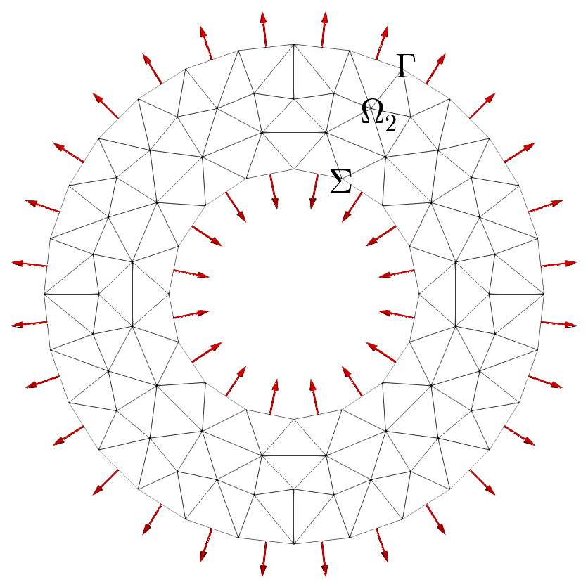
Normal vectors on crown boundaries: left (default) and right (out/towardsDomain)
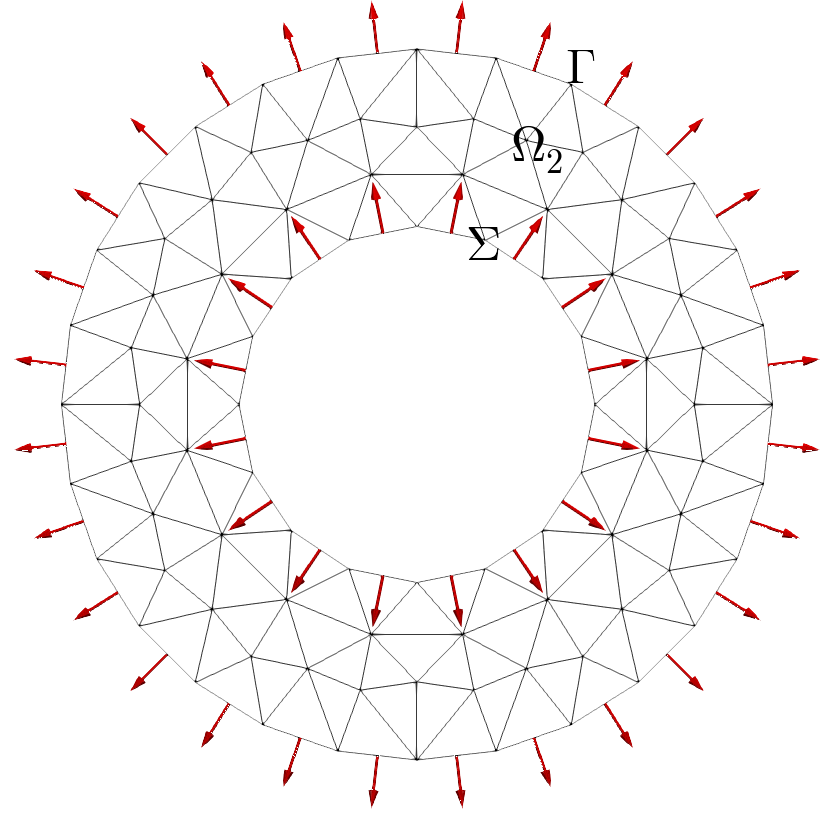
On an interface the default orientation of normal vectors is (towardsInfinite) and it can be also changed:
Disk d1(_center=Point(0.,0.), _radius=1, _hsteps=0.5, _domain_name="omg1", _side_names="sigma");
Disk d2(_center=Point(0.,0.), _radius=2, _hsteps=0.5, _domain_name="omg2", _side_names="gamma");
Mesh m(d2-d1, _shape=_triangle, _order=1);
Domain omg2=m.domain("omg2"), sigma=m.domain("sigma"), gamma=m.domain("gamma");
Domain omg1=m.domain("omg1");
saveToFile("m.vtu",m);
gamma.setNormalOrientation(); gamma.saveNormalsToFile("ngd"); // default orientation
sigma.setNormalOrientation(); sigma.saveNormalsToFile("nsd"); // on gamma and sigma
// change orientation on sigma
omg2.updateParentOfSideElements(); // necessary to update parents of side elements
sigma.setNormalOrientation(towardsDomain,omg1); sigma.saveNormalsToFile("ns");

Normal vectors on a disk (boundary and interface): left (default) and right (interface with towardsDomain omg1)
Attention
The parents of side elements are the elements of domain relating the side domain. Consequently, in case of an interface, by construction side elements have only one parents.
It is the reason why it is sometimes required to call the updateParentOfSideElements function relatively to the other domain sharing the side element; that’s the case of orientation of normal vectors of an interface.
Domain parametrization#
Domain may handle a pointer to the Geometry object related to the domain. In general, Geometry objects are not required for FE calculations
but for some applications it may be useful to have access to geometric information such as physical normal vectors, physical curvatures, …, which are provided by geometry parametrization.
For simple domain, the Geometry pointer is allocated and users have access to the parametrization:
Disk di(_center=Point(0.,0.,0.), _radius=1., _nnodes=20, _domain_name="Omega");
Mesh m(di, _generator=gmsh);
Domain omega=m.domain("Omega");
const Parametrization& par=omega.parametrization(); // polar parametrization
const Parametrization& par=omega.boundaryParametrization();
If the Geometry pointer is not set, users can attach a geometry and a parametrization:
Mesh m("mail.msh");            // load a mesh file
Domain omega=m.domain(0);      // shortcut to main domain
Geometry g=...;                // create geometry
omega.setGeometry(&g);         // attach geometry
Parametrization par(...);      // create a parametrization
omega.setParametrization(par); // attach parametrization to the domain geometry
Particular domains#
From a domain, say \(\Omega\), other domains can be constructed:
\(\Omega_s\) : the sides of a domain that is the set of geometric elements that are sides of an element of \(\Omega\),
\(\Gamma_e\) : the extension of a side domain \(\Gamma\) of \(\Omega\) that is the set of elements of \(\Omega\) having sides or nodes on \(\Gamma\),
\(\Omega_f\) : the fictitious domain that is the set of elements of a domain \(\Omega\) that intersect elements of an other domain (“intersection of domains”)
Sides domain#
Discontinuous Galerkin methods involve the set of sides (edges/faces) of elements of a plain domain.
XLiFE++ deals with such sets: either the set of all element sides or the set of all internal element sides. These domains are either created by the sidesDomain member function or by the sides function taking a domain as input argument.
The new domain is allocated in the parent domain and the previous functions return it, if it has been already built.
Rectangle R(_origin=Point(0.,0.), _xlength=1., _ylength=1., _nnodes=11, _domain_name="Omega", _side_names="Gamma");
Mesh mR(R, _shape=_triangle, _order=1, _generator=_structured);
Domain omega=mR.domain("Omega"), gamma=mR.domain("Gamma");
Domain somega=sides(omega);          // all side elements (edges) of omega
Domain isomega=internalSides(omega); // all internal side elements of omega
Note
The internal side elements domain could be constructed using minus operator:
Domain isomega=somega-gamma;
Sides domain may be used as the other domains for integrals involved in bilinear forms.
Extended domain#
The calculation of FE integrals on a side domain \(\Gamma\) of \(\Omega\) that involves non-tangential derivatives has to take into account degrees of freedom that are inside \(\Omega\). To avoid taking into account all the elements and degrees of freedom of \(\Omega\), XLiFE++ is able to construct the domain containing the elements of \(\Omega\) having a side (edge or face) located on \(\Gamma\). This is the extended domain by sides:
Sometimes some FE data only defined on a side domain \(\Gamma\) of \(\Omega\) must be extended locally to the interior of \(\Omega\). In that case XLiFE++ builds the domain containing the elements of \(\Omega\) having a vertex located on \(\Gamma\). This is the extended domain by vertices:
To build an extended domain, use the Domain:: extendDomain with a boolean argument specifying the type of extension
(true for vertex extension and false for side extension that is the default):
Rectangle R(_origin=Point(0.,0.), _xlength=1., _ylength=1., _nnodes=6, _domain_name="Omega", _side_names={"Gamma","","Sigma",""});
Mesh mR(R, _shape=_triangle, _order=1); saveToFile("mR", mR);
Domain Omega=mR.domain("Omega"), Gamma=mR.domain("Gamma"), Sigma=mR.domain("Sigma");
Domain sigma_exts=Sigma.extendDomain(false); saveToFile("sigma_exts", sigma_exts);
Domain sigma_extv=Sigma.extendDomain(true); saveToFile("sigma_extv", sigma_extv);
Regarding the extension type, the new extended domain is named side_domain_name_sextension or side_domain_name_vextension. Obviously, it can be renamed.
Fig. 114 Domain Omega#
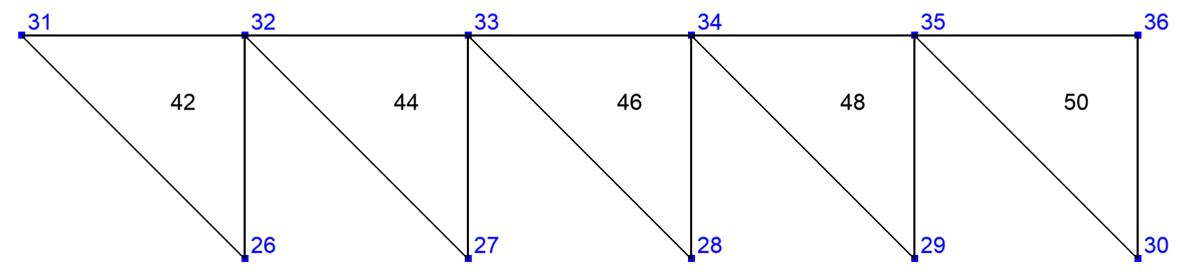
Fig. 115 Extended domain by sides#
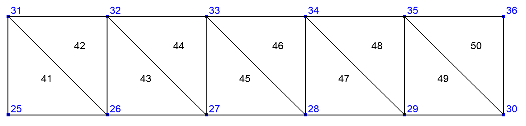
Fig. 116 Extended domain by vertices#
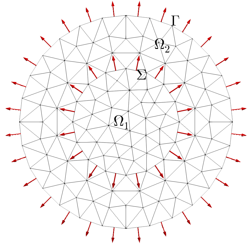
When extend an interface \(\Gamma\) between the domains \(\Omega_1\) and \(\Omega_2\), it is possible to specify if the extension concerns one of the domains \(\Omega_1\) or \(\Omega_2\) or both of them.
Rectangle R1(_origin=Point(0.,0.), _xlength=1., _ylength=1., _nnodes=6, _domain_name="Omega1", _side_names={"","Sigma","",""});
Rectangle R2(_origin=Point(1.,0.), _xlength=1., _ylength=1., _nnodes=6, _domain_name="Omega2", _side_names={"","","","Sigma"});
Mesh mR12(R1+R2, _shape=_triangle, _order=1, _generator=gmsh);
Domain omg1=mR12.domain("Omega1"), omg2=mR12.domain("Omega2"), sigma12=mR12.domain("Sigma");
sigma12.updateParentOfSideElements();
Domain int12_s=sigma12.extendDomain(false); saveToFile("int12_s",int12_s);
Domain int12_v=sigma12.extendDomain(true); saveToFile("int12_v",int12_v);
Domain int12_s1=sigma12.extendDomain(false, omg1); saveToFile("int12_s1",int12_s1);
Domain int12_v1=sigma12.extendDomain(true, omg1); saveToFile("int12_v1",int12_v1);

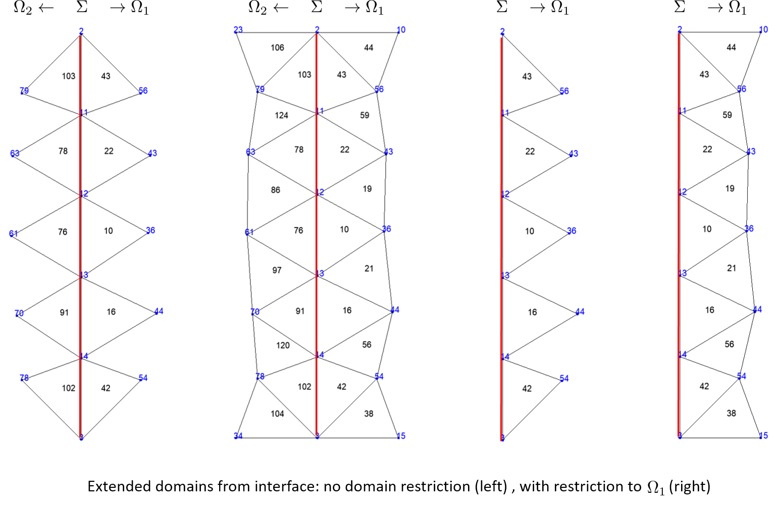
Fictitious domain#
A fictitious domain corresponds to the intersection of domains. More precisely, let \(\Gamma=\bigcup F_j\) and \(\Omega=\bigcup E_i\) two domains, fictitious domain is defined as follows:
The building process of a fictitious domain build an additional map that associates to an element of \(\Gamma\) the list of elements of \(\Omega\) intersecting it. Generally, \(\Gamma\) is of dimension n-1 when \(\Omega\) is of dimension n (curve in surface or surface in volume). This is useful to compute integrals involving unknown/test function on \(\Gamma\) and other unknown/test function on \(\Omega\). But, it also works with domains of same dimension; that allows XLiFE++ to deal with domain constructed on different meshes!
The name of the fictitious domain created is gammaName_F_omegaName.
The following code builds the fictitious domain of a circle domain immersed in a rectangle domain:
Rectangle R(_origin=Point(0.,0.), _xlength=1., _ylength=1., _nnodes=11, _domain_name="R");
Disk D(_center=Point(0.5,0.5), _radius=0.25, _nnodes=10, _domain_name="D");
Mesh mR(R, _shape=_triangle, _order=1, _generator=gmsh); // mesh of rectangle
Mesh mC(D, _shape=_segment, _order=1, _generator=gmsh);  // mesh of **circle**
Domain omega=mR.domain("R"),                 // 2d domain
       gamma=mC.domain("D");                 // 1d domain
Domain gammaF=gamma.fictitiousDomain(omega); // fictitious domain named "D_F_R"
saveToFile("omega", omega); saveToFile("gamma", gamma); saveToFile("gammaF", gammaF);
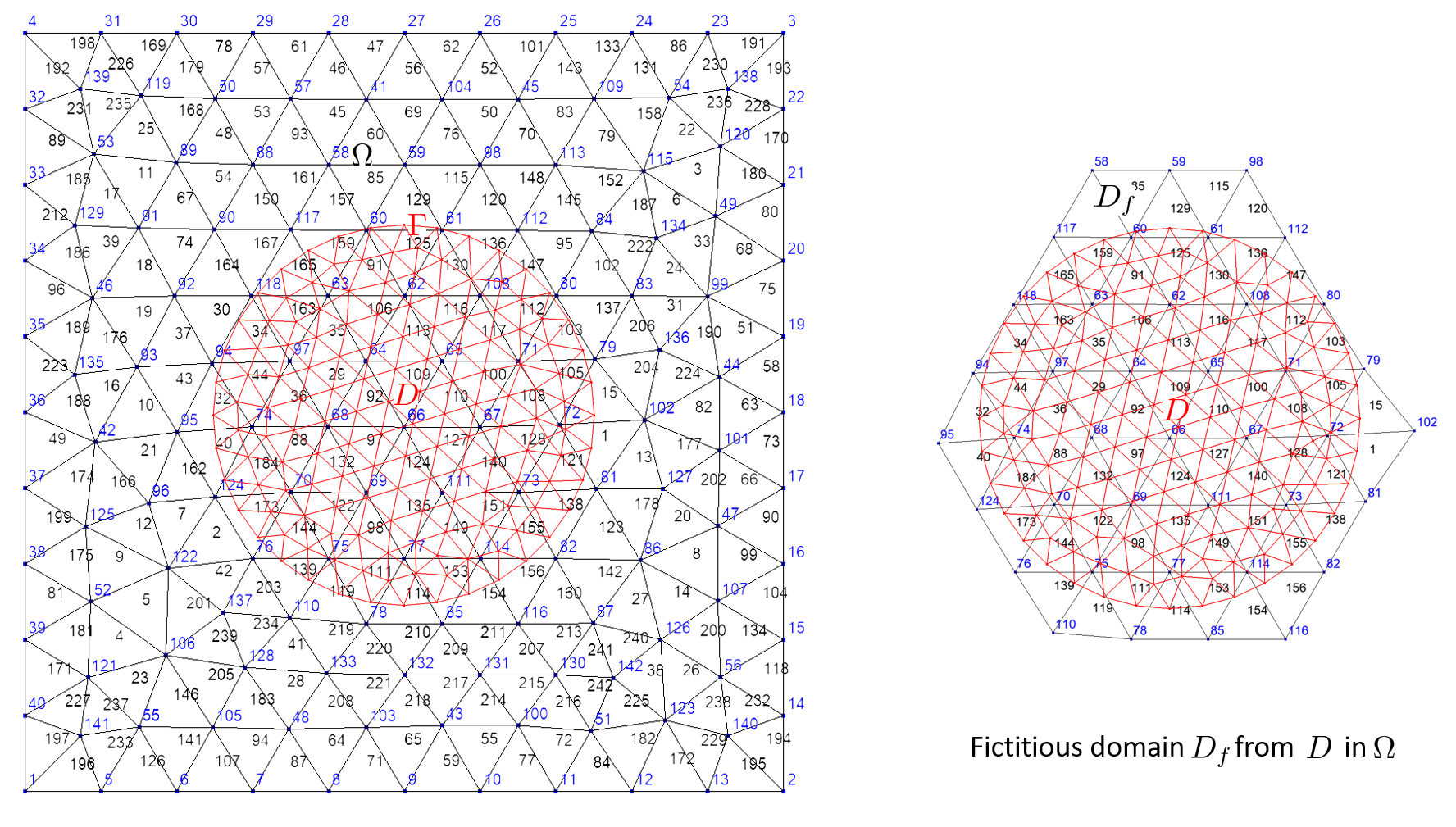
The next code (very similar) builds the fictitious domain of a disk domain immersed in a rectangle domain:
Rectangle R(_origin=Point(0.,0.), _xlength=1., _ylength=1., _nnodes=11, _domain_name="R");
Disk Di(_center=Point(0.5,0.5), _radius=0.25, _nnodes=10, _domain_name="D");
Mesh mR(R, _shape=_triangle, _order=1, _generator=gmsh); // mesh of rectangle
Mesh mD(Di, _shape=_triangle, _order=1, _generator=gmsh); // ** mesh of disk **
Domain omega=mR.domain("R"),         // 2d domain
       D=mD.domain("D");             // 2d domain
Domain Df=D.fictitiousDomain(omega); // fictitious domain named "D_F_R"
If there exists a map \(\varphi\, :\, \Gamma \rightarrow \Omega\), that is a DomainMap object (see Defining map between two domains), it will be used to build the fictitious domain as follows:
Note
Generally, users do not call directly the Domain:: fictitiousDomain. It is automatically called when it is required by some FEM/BEM calculations (see the Fictitious domain method example).
Domain operations#
Defining map between two domains#
DomainMap is a class handles a map from one domain (dom1) to an other one (dom2):
class DomainMap
{
  protected:
    const GeomDomain* dom1_p; // start domain
    const GeomDomain* dom2_p; // end domain
    Function map1to2_;        // map function from dom1 to dom2
  public:
    bool useNearest;          // use nearest method instead of locate method after mapping
    string_t name;            // a unique name
};
The Function objet map1to2_ must refer to a c++ function of the form:
Reals funMap(const Point& p, Parameters& pa = defaultParameters);
Domain maps can be used in different context: periodicity condition, transport of a function from one domain to an other domain (spectral basis for instance, see ?).
Sometimes, the transporting point has to be localized in the arrival domain using localization function that proposed two methods:
an exact localization or an approximate localization using the nearest point or element. This is the purpose of the DomainMapuseNearest boolean variable.
The DomainMap holds the list of all domain maps so it’s easy to find a map if it’s been defined.
To define a domain map, the simplest way consists in using the defineMap function:
Reals transxm1(const Point& p, Parameters& pa = defaultParameters)
{
  Reals q={p(1)-1,p(2)}; return q; // translation (x,y) -> (x-1,y)
}
...
Rectangle R(_origin=Point(0.,0.), _xlength=1., _ylength=1., _nnodes=6, _domain_name="Omega", _side_names={"","x=1","","x=0"});
Mesh mR(R, _shape=triangle);
Domain omega=mR.domain("Omega"), sigma=mR.domain("x=1"), gamma=mR.domain("x=0");
defineMap(sigma, gamma, transxm1); // define DomainMap with useNearest=false
Other possibilities are
defineMap(sigma, gamma, transxm1, true);           // define with useNearest=true
defineMap(sigma, gamma, transxm1, "sigma->gamma"); // define with a name, useNearest=false
defineMap(sigma, gamma, transxm1, "sigma->gamma", true); // define with a name, useNearest=true
When no name passed, the name of the domain map is “dom1_name–>dom2_name”. Name has to be unique!
Some processes (e.g. processing periodic conditions between two boundaries) requires the map related one boundary (dom1) to the other one (dom2).
XLiFE++ uses the findMap function, that’s either find a map related dom1 to dom2 if it has been defined or try to build one (only translation).
Important
As the maps are searched in the global list of maps using the names of domain, there can be only one active map between two domains!
Hint
When dealing with curved domains, generally meshed with P1,P2, … elements, you can use some natural maps from one domain to the other (think about the scaling transformation of a circle to another circle whereas the circles are approximated by polygons). In that case, points are transported using the given geometrical transformation and an additional projection to guarantee that the image points belong to the arrival domain. Obviously, the projection induces an error related to the mesh size.

Merging domains#
XLiFE++ can merge domains coming from the same mesh and having the same dimension. The process creates a new DomainMap object by
merging the list of geometric elements (that are supposed to non overlap)
merging the list of nodes (duplicate nodes are not reduced)
To merge domains use the merge functions:
Domain merge(Domain dom1, Domain dom2, Domain dom3, ..., String name);
The number of domains can be up 20.
The following code illustrates the merging of two 2d domains:
Rectangle R(_origin=Point(0.,0.), _xlength=1., _ylength=1., _nnodes=5, _domain_name="Omega0");
Disk Dp(_center=Point(1.,0.5), _radius=0.5, _angle1=-pi_/2, _angle2=pi_/2, _nnodes=3, _domain_name="Omega+");
Disk Dm(_center=Point(0.,0.5), _radius=0.5, _angle1=pi_/2, _angle2=3*pi_/2, _nnodes=3, _domain_name="Omega-");
Mesh mRD(R+Dm+Dp, _shape=triangle);
Domain omg0=mRD.domain("Omega0"), omgp=mRD.domain("Omega+"), omgm=mRD.domain("Omega-"),
omega=mRD.domain("#Omega");      // full mesh domain
Domain omg0p=merge(omg0, omgp, "omg0p");
saveToFile("omg0", omg0); saveToFile("omgp", omgp); saveToFile("omgm", omgm);
saveToFile("omg0p", omg0p); saveToFile("omega", omega);
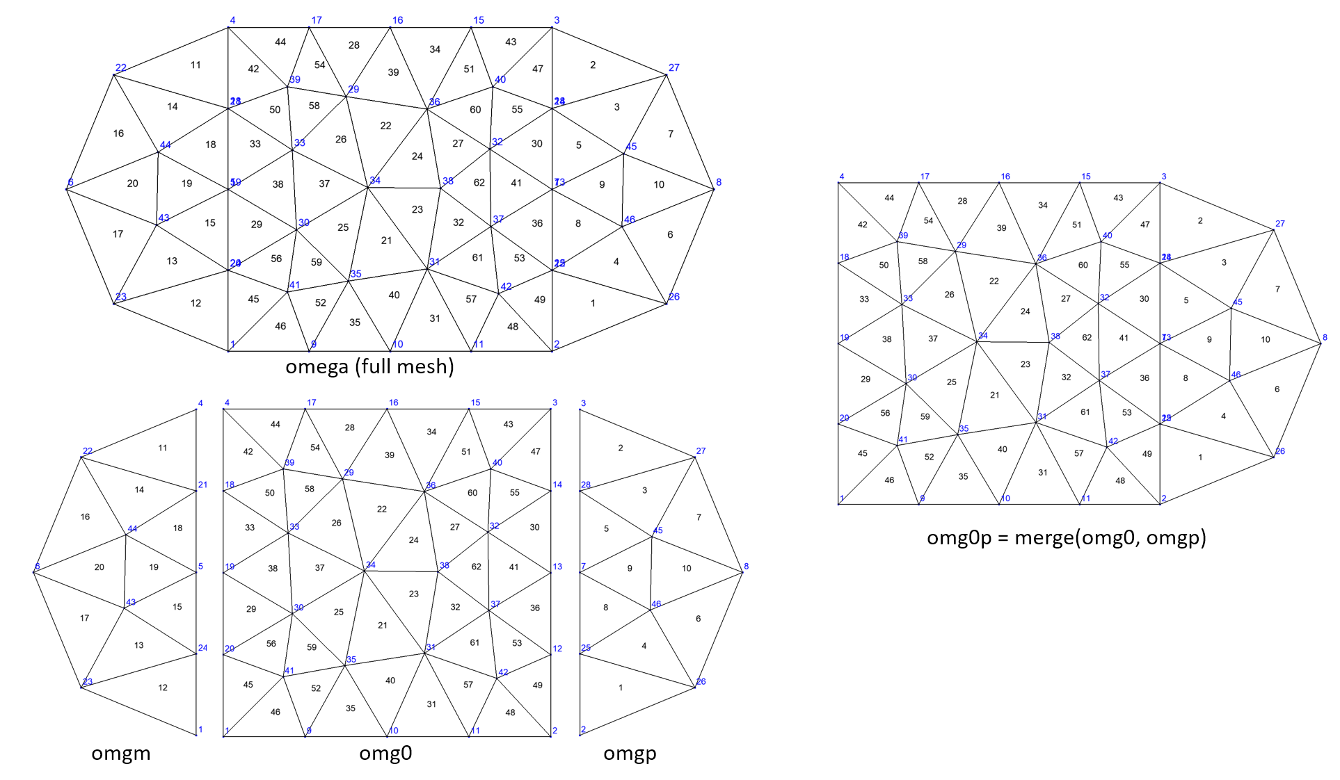
Fig. 117 Example of domains merging#
Note that nodes on interface are duplicated in the original mesh done by Gmsh and remain duplicated in the merging process!
Important
The “full” domain, consisting of all mesh elements is always constructed. It can be accessed from the mesh using either the name “Omega” or “#Omega” if “Omega” was used to name another domain in the mesh. Therefore, it is not useful to merge all subdomains to get the “full” domain.
In an alternative way, the operator + may be used to merge two domains:
Domain omg0p = omg0 + omgp; // named "0mega0 + Omega+"
Hint
When there are more than 2 domains, it is advised to not use operator + because temporary useless domains are created!
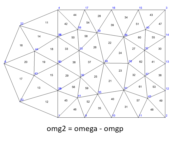
Domains difference#
The difference between two domains, say \(\Omega_1\) and \(\Omega_2\) of same dimension, is the domain defined as
There are two ways to get the new domain \(\Delta\):
Domain delta = omega1.removeElts(omega2, [name]);
Domain delta = omega1-omega2;  // named "omega1 - omega2"
Using domains defined in merging example, the code
Domain omg2=omega-omgp; saveToFile("omg2",omg2);
gives the same domains as omg0 + omgm:
Updating domains#
In some numerical methods, geometric domains can changed and have to be redefined during an iterative process (think about level set methods for instance).
XLiFE++ provides a general tool to do this : the rebuild function with the following prototypes, rebuiding 2 domains and optionnally 1 or 2 side domains:
void rebuild(dom1, comparisonFun1, dom2, comparisonFun2);
void rebuild(dom1, comparisonFun1, dom2, comparisonFun2, sdom);
void rebuild(dom1, comparisonFun1, dom2, comparisonFun2, sdom1, sdom2);
The comparisonFun are objects of the ComparisonFunction class which handles boolean criteria involving either _color or _index element property, for instance:
ComparisonFunction cr1 = (_color == 0) && (_index>0),
                   cr2 = (_color>0);
Obviously, the rebuild function works in conjunction with the setColor function. How does it work?
the dom1 is rebuilt from elements for which the comparisonFun1 is true (e.g. elements with their color property set to 0),
the dom2 is rebuilt from elements for which the comparisonFun2 is true (e.g. elements with their color property positive),
when side domains are specified, they are updated if dom1 or dom2 have changed.
There exists also a version of the rebuild function that works with lists of domains, of comparison functions and of side domains:
void rebuild(vector<GeomDomain*>& doms, vector<ComparisonFunction<> >& crs, set<GeomDomain*>& sidedoms);
The next example shows how to rebuild two domains \(\Omega_1\), \(\Omega_2\), using the coloring rule on an element (\(x_i\) abcissa of the i-th vertex of element):
Real colorRule(const GeomElement& gelt, const std::vector<Real>& val)
{
  Real mx=*std::max_element(val.begin(),val.end());
  if (mx>=1.5) return 1; else return 0;
}
...
Rectangle R1(_origin={0.,0.}, _xlength=1., _ylength=1., _hsteps=0.1, _domain_name="Omega_1");
Rectangle R2(_origin={1.,0.}, _xlength=1., _ylength=1., _hsteps=0.1, _domain_name="Omega_2");
Mesh mR12(R1+R2, _shape=triangle);
Domain omega=mR12.domain("Omega"), omega1=mR12.domain("Omega_1"),
                                   omega2=mR12.domain("Omega_2");
Space V(_domain=omega, _interpolation=P1, _name="V"); Unknown u(V, _name="u");
TermVector tv(u, omega, _x);    // vector on mesh vertices containing x_i
setColor(omega, tv, colorRule); // compute color according to the colorRule
ComparisonFunction<> cr1= _color==0., cr2= _color>0.; // rebuild criteria
rebuild(omega1, cr1, omega2, cr2); // rebuild omega1 (elements with color = 0) and omega2 (elements with color > 0)
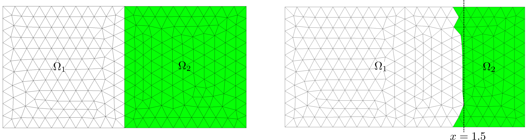
Fig. 118 Original domains and rebuilt domains.#
Attention
The rebuild function does not modify geometric elements!
Note
In an advanced use, coloring elements can be done in an ‘direct’ way:
for (auto gp : omega.meshDomain()->geomElements)  // loop on elements of omega
{ gp->color= ... }
or
for (Number k=1; k<=omega.numberOfElements(); k++)  // loop on elements of omega
{ omega.element(k)->color= ... }
Partitioning a domain#
The partition of a domain is a set of non-overlapping sub-domains covering the original domain \(\Omega\):
Here \(\Omega\), \(\Omega_i\) are considered as sets of geometric elements of same dimension.
XLiFE++ provides Domain::partition member function to create a partition of a domain:
dom.partition(par1,[par2], [par3],...);
where par1, par2, … (up to 10) are partitioning parameters passed using key/value:
_nbParts: number of partitions (2 by default)_partmesh: type of partition:dual(default) ornodal_ncommon: number of common nodes that two elements must have in order to put an edge between them in the dual graph (default 1)._ptype: partitioning method:rec(recursive bisectioning) orkway(default)_ctype: matching scheme to be used during coarsening:rm(random matching) orshem(sorted heavy-edge matching, default)_iptype: scheme to compute the initial partitioning (only when_ptype=rec):grow(greedy strategy, default) oriprandom(random)_objtype: partitioning’s objective function (only when_ptype=kway):cut(edge cut minimization, default) orvol(total communication volume minimization)_rtype: refinement algorithm:fm(FM-based cut refinement, default),greedy(greedy strategy),sep2sidedorsep1sided
When executing the Domain::partition function on a domain, say omega object , a PartitionData object is allocated in omega
(partitionData_p pointer) and Domain::partitionData function gives access to this object. This object provides much information on the partition:
|
|
list of sub-domains of the partition, named “omegaName_i” |
|
|
map element number -> partition number |
|
map vertex number -> partition number |
|
|
|
list of numbers of vertices on interfaces |
|
|
list of numbers of element affecting the interfaces |
|
|
list of side elements on interfaces |
The mesh sub-domains of the partition are available using Mesh::domain function with the name: omegaName_i.
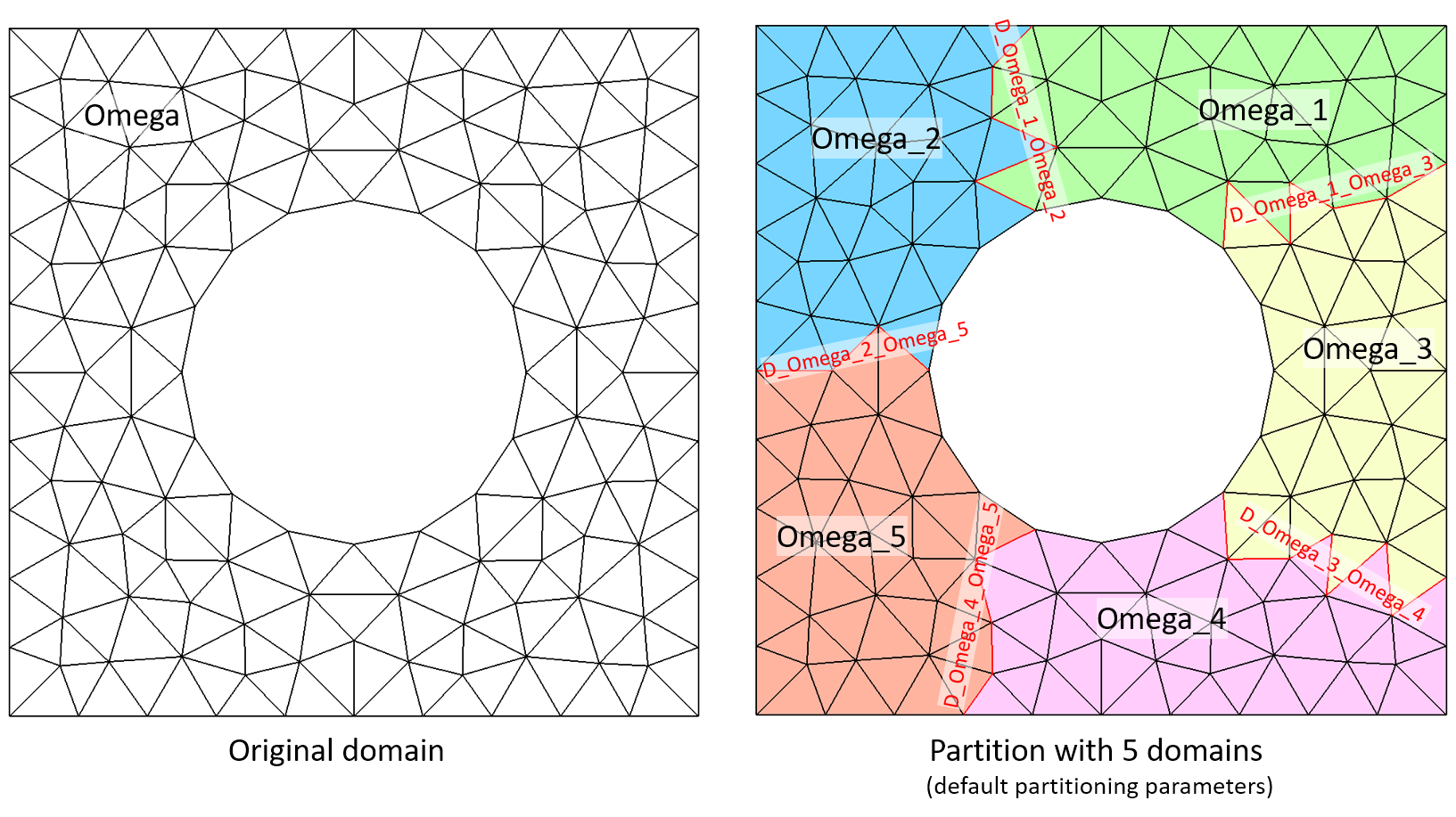
The interface between sub-domains are also created as Domain objects and they are named: D_omegaName_i_omegaName_j (i<j).
The following example illustrates how Domain::partition function works (5 subdomains and default partitioning parameters):
Rectangle Rp(_origin=Point(0.,0.), _xlength=1., _ylength=1., _hsteps=0.1, _domain_name="Omega");
Disk Di(_center=Point(0.5,0.5), _radius=0.25, _hsteps=0.1);
Mesh mRpDi(Rp-Di, _shape=triangle);
Domain omega=mRpDi.domain("Omega");
omega.partition(_nbParts=5);
saveToFile("mRpDi.msh", mRpDi);  // to visualize partitions with gmsh
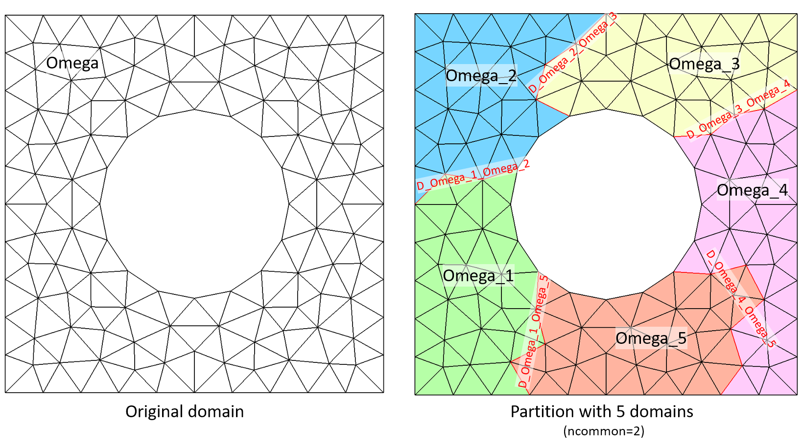
The same example but using _ncommon=2, that makes interfaces more regular:
omega.partition(_nbParts=5, _ncommon=2);
Sum up#
Domain dom=mesh. |
shortcut to the domain of a mesh by its name or number |
dom. |
access to |
dom. |
access to geometry pointer and set geometry pointer |
true if parametrization allocated |
|
dom. |
return and set parametrization |
return ansd set boundary_parametrization |
|
dom. |
true if a side domain, a domain of sides and an interface (shared side domain) |
dom. |
number of geometric elements of domain |
dom. |
return the element order (>0) |
dom. |
set material ID (>0) for all elements of domain |
|
update color property of all elements of omega according to a coloringRule using tv values |
dom. |
access to and set the colorFlag status |
dom. |
return and set the normal vectors orientation of a side domain |
dom. |
return normal vector (as a |
dom. |
compute domain statistics and return the measure (length, surface or volume) of domain |
update parents elements of the side elements of a side domain |
|
dom. |
access to sides domain, extended domain and fictitious domain (created if not exists) |
|
access to the sides/internalsides domain of dom (created if not exists) |
|
|
|
merge domains (up to 20) of same dimension, create a new one |
dom1 + dom2 |
same as merge of two domains |
dom. |
remove from current domain some elements of an other domain, creating domain if different from the current one |
dom1 - dom2 |
create domain from elements of dom1 not in dom2 (same mesh and same dimension) |
|
rebuild some domains according to some rules ( |
dom. |
do a partition of the domain according to some partitioning rules (allocate a |
dom. |
display domain information (increase with verbose level) |
dom. |
display information about all the domains in memory |
dom. |
export normal vectors to vtk file (paraview) |
dom. |
export element colors to vtk file (paraview) |
dom. |
access to the meshdomain ( |
dom. |
access to k-th element (k>=1) ( |
dom. |
access to |
dom. |
return the element ( |
dom. |
return the nearest element ( |