

Transformations and extrusions#
Transformations on meshes#
XLiFE++ allows you to apply geometrical transformations on Mesh.
Then, if you want to apply a transformation and modify the input object, you can use one of the following functions:
translateto apply a translationrotate2dto apply a 2d rotationrotate3dto apply a 3d rotationhomothetizeto apply a homothetypointReflectto apply a point reflectionreflect2dto apply a 2d reflectionreflect3dto apply a 3d reflection
For instance:
Segment s(_v1=Point(0.,0.,0.), _v2=Point(0.,0.,0.), _nnodes=10, _domain_name="S1");
s.translate(_direction={0.,0.,1.});
Please see Geometrical transformations for definition and use of transformations routines.
However, if you want now to create a new object by applying a transformation on a geometry, you should use one of the related external functions instead.
For instance:
Segment s(_v1=Point(0.,0.,0.), _v2=Point(0.,0.,0.), _nnodes=10, _domain_name="S1");
Segment s2=translate(s, _direction={0.,0.,1.});
Important
When transforming a Mesh, domain names are changed. Indeed, the transformation adds a suffix “_prime”.
Mesh extrusion#
Instead of extruding a geometry, it is possible to extrude a 1d or 2d mesh (section) by applying a geometric transformation to it. To do this, use the function extrude.
Mesh extrude(s_mesh, tranformation, [[key-value1,[key-value2]], ...])
where
-
the mesh of the section (
s_mesh) may be eithera 1d mesh made of segments, the extruded mesh is then a 2d mesh made of quadrangles
a 2d mesh made of triangles or quadrangles, the extruded mesh is then a 3d mesh made of prisms or hexahedra.
-
the transformation may be either
a
Transformationobject handling a tranlsation, a rotation or a combination of basic transformations; the same transformation being applied to each section of the extrusiona collection of
Transformationobjects, each transformation being applied to one section of the extrusion. The number of transformations has to be equal to the number of layers of the extrusion.-
a c++ function describing the extrusion path, with the following form:
Vector<real_t> path(const Point&, Parameters&, DiffOpType);
Key values (up to 5) can be specified to control the extrusion process:
_layersto give the number of layers (mandatory)_centerto give the center of rotation when using a curve parameterization (computed by default as the barycenter of the input section)_init_transformationto specify a tranformation to apply to the reference section before extruding it (none by default)_naming_domainto control the naming of domains (noName,globalName,indexedName)_naming_sectionto control the naming of sections(noName,globalName,indexedName)_naming_sideto control the naming of boundaries (noName,globalName,indexedName)
The meaning of the naming arguments is
noName: no domains, no section domains, noboundaries domains are created. The full domain is always created and named “#Omega”.globalName: only some global extruded domains, a domain including end sections or some global boundary domains included all boundary domains are created (domain names are postfixed _e).indexedName: for each layer, one extruded domain, section domain or boundary domains are created (domain names are postfixed _0, _1,… or _e0, _e1, …).

The following figure illustrates the naming rules of domains when meshing a tubular domain using crown mesh extrusion:
Disk dext(_center=Point(0.,0.), _radius=1., _nnodes=20, _domain_name="Omega", _edge_names="Sigma");
Disk dint(_center=Point(0.,0.), _radius=0.5, _nnodes=10, _edge_names="Gamma");
Mesh crown(dext-dint, _generator=gmsh);
Mesh tube(crown, Translation(0,0,.1), _layers=10, _naming_domain=1, _naming_section=1, _naming_side=1);
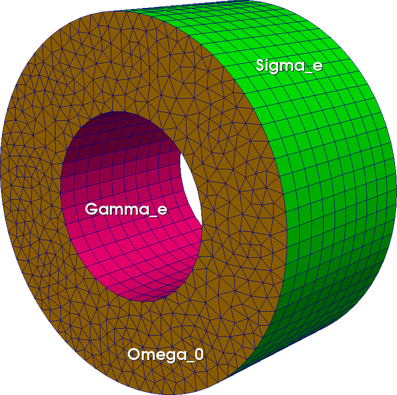
Fig. 113 Tube prismatic mesh from extrusion of a crown mesh#
Example 1: extrusion of a disk using a rotation leading to a torus
Here a 3d rotation of angle \(\frac{\pi}{20}\) is applied to each section and _layers key-value specifies the number of layers (40). Note that in that case, a full turn is done and the last section coincides with the first section, the nodes being not duplicated.
..code:
Mesh mdi(Disk(_center=Point(0.,0.), _radius=1., _nnodes=8), _shape=_triangle);
Mesh m=extrude(mdi, Rotation3d(_center=Point(3.,0.,0.), _axis={0.,1.,0.}, _angle=2*pi_/40), _layers=40);
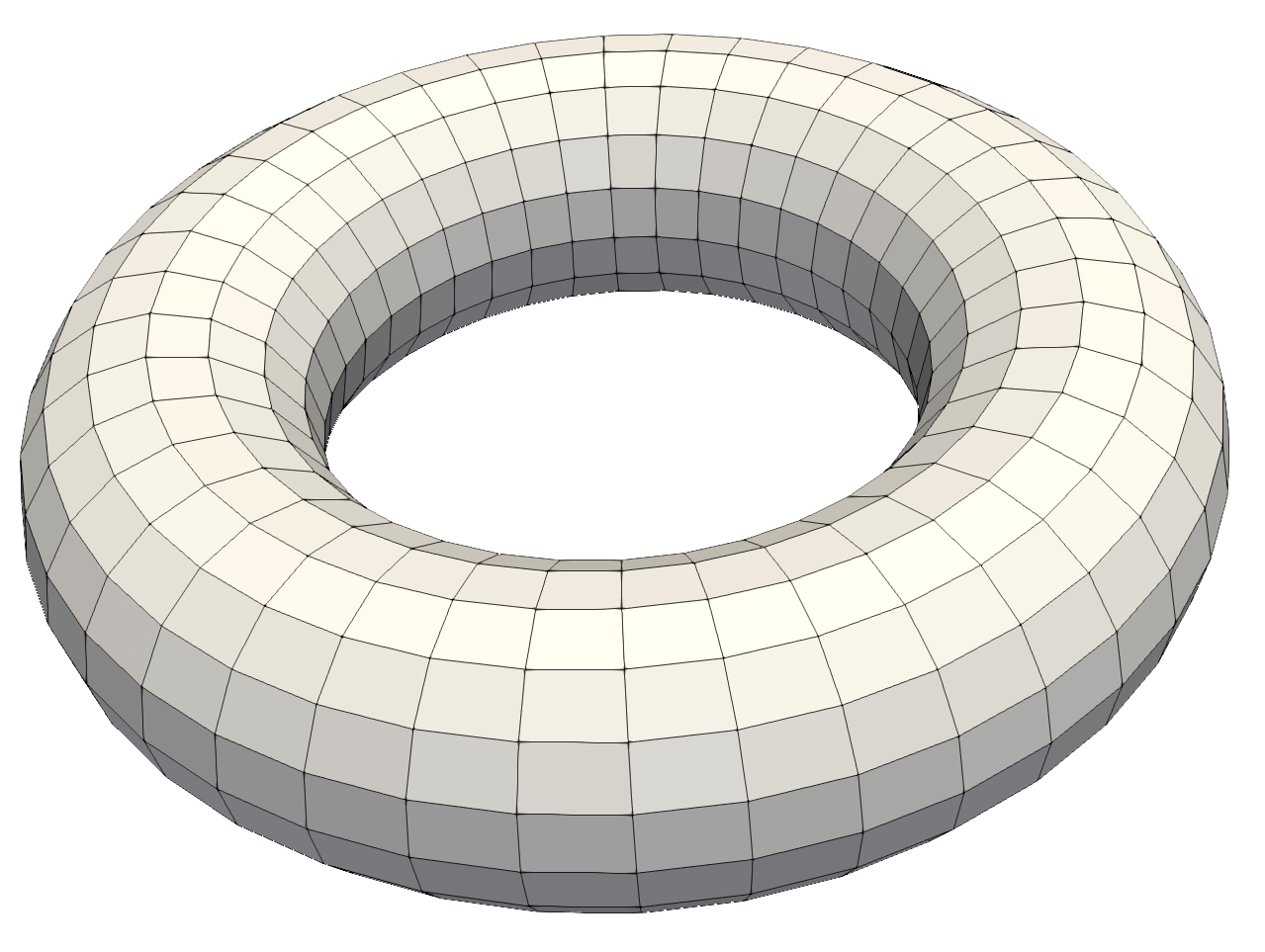
Fig. 114 Extrusion using a rotation leading to a torus#
Example 2: extrusion of a rectangle using a combination of transformations
The transformation may be a combination of transformations (see Geometrical transformations for more details):
Mesh mr(Rectangle(_xmin=0, _xmax=1, _ymin=1, _ymax=3, _nnodes=Numbers(6, 10)), _shape=_triangle, _order=1, _generator=_structured);
Mesh m=extrude(mr, Translation(0.,0.1,0.)*Rotation3d(Point(3.,0.,0.), Reals(0.,1.,0.), 2.5*pi_/100), _layers=100);
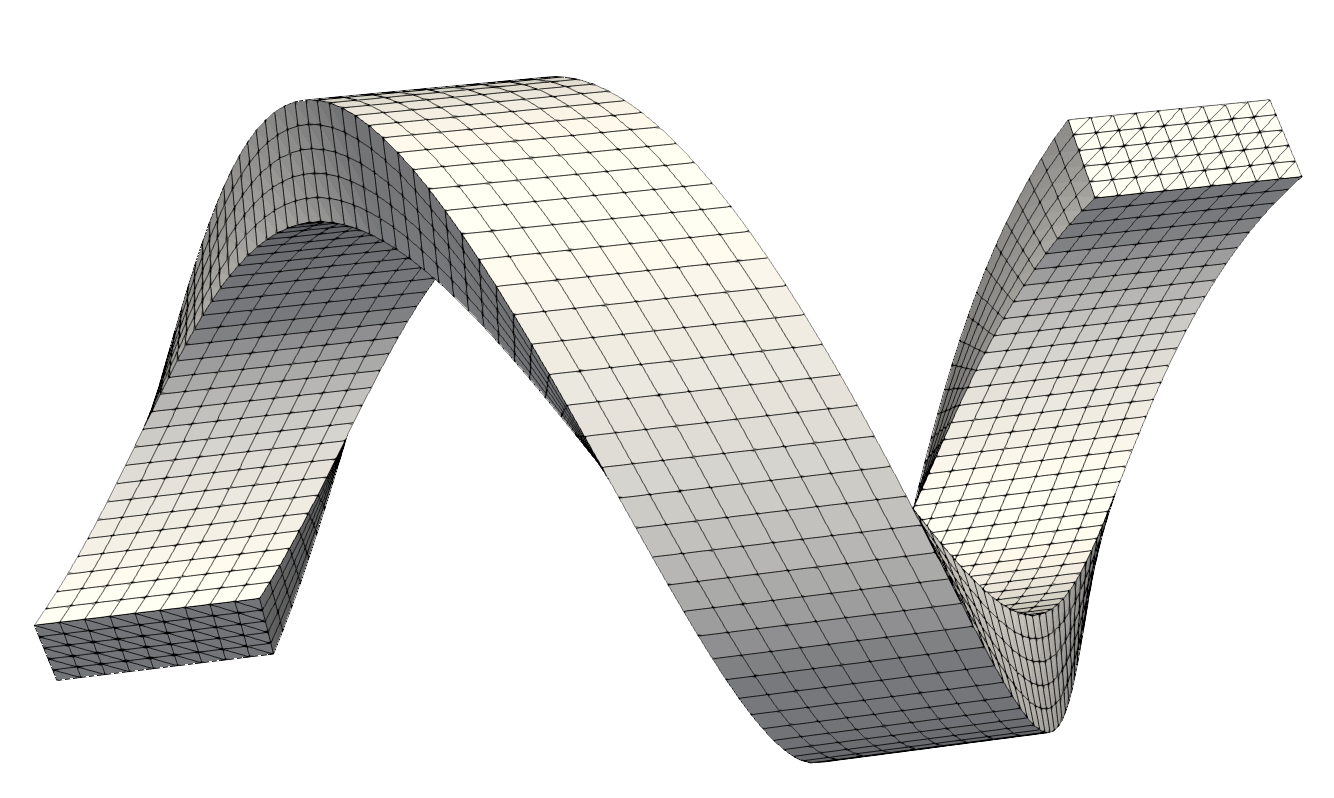
Fig. 115 Extrusion using a combination of transformations#
Example 3 : extrusion of a rectangle using a list of transformations
Instead of specifying a transformation, it is possible to specify the list of transformations to apply to the sections:
Mesh mr(Rectangle(_xmin=0, _xmax=1, _ymin=1, _ymax=3, _nnodes=Numbers(6, 10)), _shape=_triangle, _order=1, _generator=_structured);
Translation tran(0.2,0.,0.);
Rotation3d rot1(Point(3.,0.,0.),Reals(0.,1.,0.),pi_/40);
Rotation3d rot2(Point(5.,0.,6.),Reals(0.,1.,0.),-pi_/40);
std::vector<Transformation*> trs(50);
for (number_t i=0; i<20; i++)  { trs[i]=&rot1; trs[i+30]=&rot2; }
for (number_t i=0; i<10; i++)  { trs[i+20]=&tran; }
Mesh m=extrude(mesh2dP1, trs, _naming_domain=1);
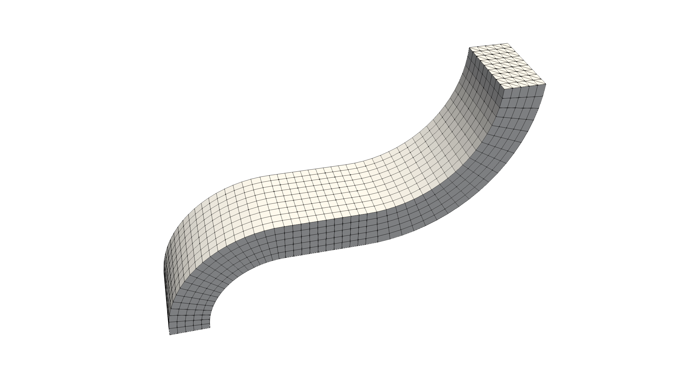
Fig. 116 Extrusion using a list of Transformations#
Example 4 : extrusion of a disk using a path parametrization
To deal with more general extrusions, a C++ function giving the parametrization of the extrusion path: \(t\in[0,1]\rightarrow \gamma(t)\in \mathbb R^d\) can be given. Be cautious, the parametrization has to statisfy \(\gamma(0)=0\) and \(\gamma'(0)=n_s\) where \(n_s\) is the normal vector to the section to be extruded. The extrusion works as following:
the nodes \(M_0\) of section \(S_0\) are translated: \(M_k=M_0+\gamma(\frac{k}{n})\)
then, a rotation defined from the center \(C_k=C_0+\gamma(\frac{k}{n})\) and the two vectors \(n_0,\ \gamma'(\frac{k}{n})\) is applied to the nodes \(M_k\)
By default, the rotation center \(C_0\) is the barycenter of all nodes of the section \(S_0\) but it can be changed using the key-value _center. Note that this process guarantees that all sections are orthogonal to the extrusion curve.
Reals gamma(const Point& P, Parameters& par, DiffOpType dop)
{
  real_t t=P(1);
  if (dop==_dt) return Reals{16*pi_*std::sin(4*pi_*t), 0., 40.};
  return Reals{2*(1-std::cos(4*pi_*t)), 0., 40*t};6
}

Mesh mdi(Disk(_center=Point(0.,0.), _radius=1., _nnodes=8), _shape=_triangle, _generator=subdiv);
Mesh m=extrude(mdi, gamma, _layers=100);
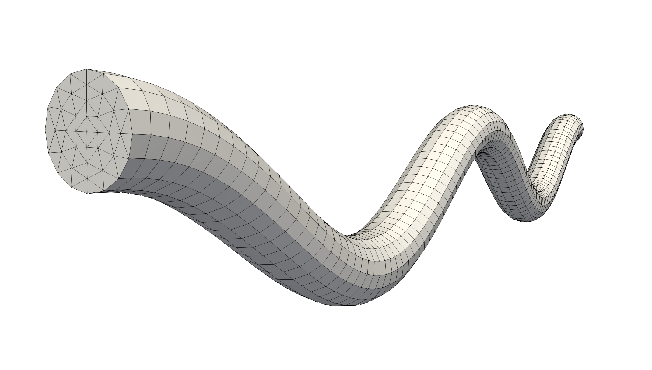
Fig. 117 Extrusion using a curve parametrization#
Tip
The orientation of normal vector to the section to be extruded is not predictable. But using the routine setNormalOrientation it can be set:
Mesh mdi(Disk(_center=Point(0.,0.), _radius=1., _nnodes=8), _shape=_triangle);
mdi.domain(0).setNormalOrientation(_towardsInfinite,Point(0.,0.,-1.));
where the given point (here (0.,0.,-1.)) specifies an ‘interior’ point.
Danger
If curvature radius is too small compared to the section size, the extrusion process may lead to incoherent domain!