

Mesh tools#
Mesh refinement#
It is possible to refine an existing mesh of order 1: a new mesh is created using the subdivision generator mentioned above. It is a uniform refinement, say, all the elements are subdivided in a same way. The corresponding constructor is defined as follows:
Disk d(_center=Point(0.,0.), _radius=1., _nnodes=5);
Mesh md(d, _generator=gmsh, _shape=triangle);
Mesh md1(md, _refinement_depth=1);
Mesh md2(md, _refinement_depth=2);
This builds the meshes md2 and md2 which are obtained by subdividing, respectively, once and twice the mesh md:
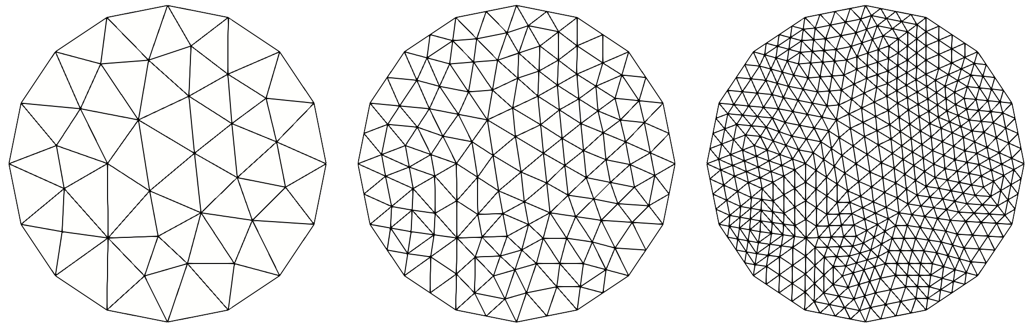
Fig. 118 Refine once and twice the P1 mesh of a disk.#
The optional keys are:
_refinement_depth: the refinement depth of the subdivision generator. 0 means no refinement (the default value).
_order: by using it, it possible to increase the order of the refined mesh (defaut value is 1).
Note
Up to now, there is no adaptative refinement tool!
Splitting mesh elements#
Sometimes it may be useful to split elements into elements of another type, for instance to produce mesh of pyramids that are not provided by standard meshing software products. To do this, the routine split is available:
Cuboid c(_xmin=0, _xmax=1, _ymin=1, _ymax=3, _zmin=1, _zmax=5, _nnodes={3, 5, 9});
Mesh meshQ1(c, _shape=hexahedron, _generator=structured, _name="Q1 mesh");
Mesh meshPyramid=split(meshQ1, pyramid, "Py1 mesh");
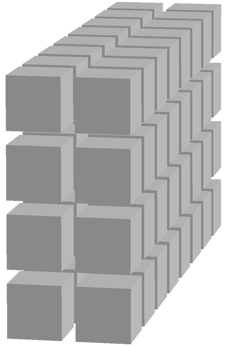

Fig. 119 Hexahedron mesh split to pyramid mesh.#
Note
Up to now, only one splitting process is available: hexahedron of order 1 into six pyramids of order 1, based on the hexahedron faces and the centroid of the hexahedron as tip.
Merging meshes#
It is possible to merge some meshes of same dimension. They can share common parts or common boundaries but with same elements/nodes. If elements or nodes on common parts do not coincide, the resulting mesh would not be conform to do finite element approximations. The merging process combines the elements and nodes of the meshes, eliminating duplicate elements or duplicate nodes. Domains with same name are also merged, names being preserved. The new whole domain is created with default name #Omega or one given and shared boundary domains are merged on demand (default).
Mesh m1(...);
Mesh m2(...);
Mesh m3(...);
m1.merge(m2,[mergeSharedBoundary=true],[name="#Omega"]);//merging m2 with m1
m1.merge(m3,[mergeSharedBoundary=true],[name="#Omega"]);//merging m2, m3 with m1
Mesh m = merge(m1,m2,m3,[mergeSharedBoundary = true],[name = "#Omega"]);
// alternate syntax merging m1,m2 and m3 in a new mesh m (up to 5 meshes)
As an example:
Rectangle R1(_xmin=0, _xmax=1, _ymin=1, _ymax=3, _nnodes={6,10});
Rectangle R2(_xmin=1, _xmax=2, _ymin=1, _ymax=3, _nnodes={3, 5});
Mesh mP1(R1, _shape=triangle, _generator=structured, _name="P1 mesh");
Mesh mQ1(R2, _shape=quadrangle, _generator=structured, _name="Q1 mesh");
Mesh mP1Q1 = merge(mP1,mQ1);

Rectangle R3(_xmin=1, _xmax=2, _ymin=1, _ymax=3, _nnodes={6,10});
Mesh mQ1a(R3, _shape=quadrangle, _generator=structured, _name="Q1 mesh a");
mP1Q1 = merge(mP1,mQ1a);
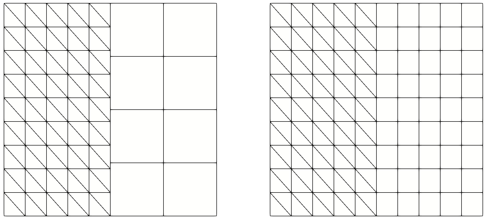
Fig. 120 Non-conforming and conforming merging of a triangular mesh with a quadrangular mesh.#
In the merging process the following rules are applied:
all named domains of original meshes are preserved, with the same names,
if two different domains have the same name, they are merged,
-
if two side domains define an interface (same nodes) in the merging process and do not have the same name, say domname1 and domname2:
if
mergeSharedBoundaryis true, a new domain named domname1_domname2 is created and the original ones are deletedif
mergeSharedBoundaryis false, the original domains domname1 and domname2 are retained
if two side domains define an interface in the merging process and have the same name, say domname, only one domain remains, again named domname and regarded as an interface.
Attention
If two side domains with the same name have a common part which is not the whole side domain, the merging process fails and an error is raised.
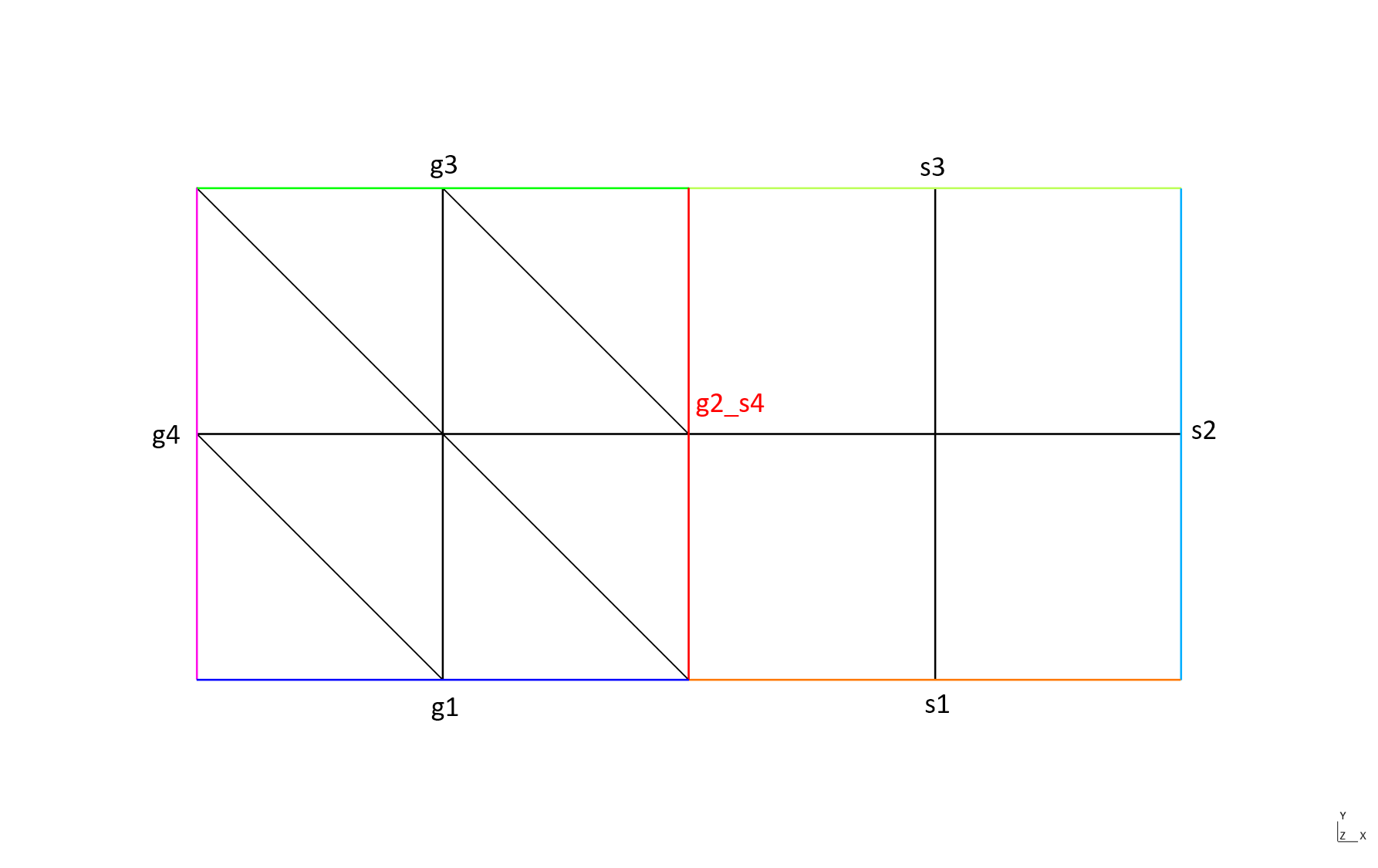
The following example shows the merging of two rectangles with different side names (mergeSharedBoundary set to true by default):
Rectangle R1(_xmin=0, _xmax=1, _ymin=0, _ymax=1, _nnodes={3,3}, _domain_name="omega", _edge_names={"g1","g2","g3","g4"});
Rectangle R2(_xmin=1, _xmax=2, _ymin=0, _ymax=1, _nnodes={3,3}, _domain_name="omega", _edge_names={"s1","s2","s3","s4"});
Mesh mR1P1(R1, _shape=_triangle, _order=1, _generator=_structured);
Mesh mR2Q1(R2, _shape=_quadrangle, _order=1, _generator=_structured);
Mesh mR1R2=merge(mR1P1,mR2Q1);
producing the domains:
Domain 'g1' of dimension 1 from mesh 'P1 mesh of [0,1]x[0,1] + Q1 mesh of [1,2]x[0,1]', orientation not computed, 2 elements
 geometric side element 13: side 3 of element 1
 geometric side element 14: side 3 of element 3
Domain 'g2_s4' of dimension 1 from mesh 'P1 mesh of [0,1]x[0,1] + Q1 mesh of [1,2]x[0,1]', orientation not computed, 2 elements
 geometric side element 29: side 2 of element 4, side 4 of element 9
 geometric side element 30: side 2 of element 8, side 4 of element 11
Domain 'g3' of dimension 1 from mesh 'P1 mesh of [0,1]x[0,1] + Q1 mesh of [1,2]x[0,1]', orientation not computed, 2 elements
 geometric side element 17: side 3 of element 6
 geometric side element 18: side 3 of element 8
Domain 'g4' of dimension 1 from mesh 'P1 mesh of [0,1]x[0,1] + Q1 mesh of [1,2]x[0,1]', orientation not computed, 2 elements
 geometric side element 19: side 2 of element 1
 geometric side element 20: side 2 of element 5
Domain 's1' of dimension 1 from mesh 'P1 mesh of [0,1]x[0,1] + Q1 mesh of [1,2]x[0,1]', orientation not computed, 2 elements
 geometric side element 21: side 1 of element 9
 geometric side element 22: side 1 of element 10
Domain 's2' of dimension 1 from mesh 'P1 mesh of [0,1]x[0,1] + Q1 mesh of [1,2]x[0,1]', orientation not computed, 2 elements
 geometric side element 23: side 2 of element 10
 geometric side element 24: side 2 of element 12
Domain 's3' of dimension 1 from mesh 'P1 mesh of [0,1]x[0,1] + Q1 mesh of [1,2]x[0,1]', orientation not computed, 2 elements
 geometric side element 25: side 3 of element 11
 geometric side element 26: side 3 of element 12
Domain 'omega' of dimension 2 from mesh 'P1 mesh of [0,1]x[0,1] + Q1 mesh of [1,2]x[0,1]', orientation not computed, 12 elements
 geometric element 6 (material 0, color 0, twin 0): triangle_Lagrange_1, orientation +0, linear map, measure = 0.125
 ...
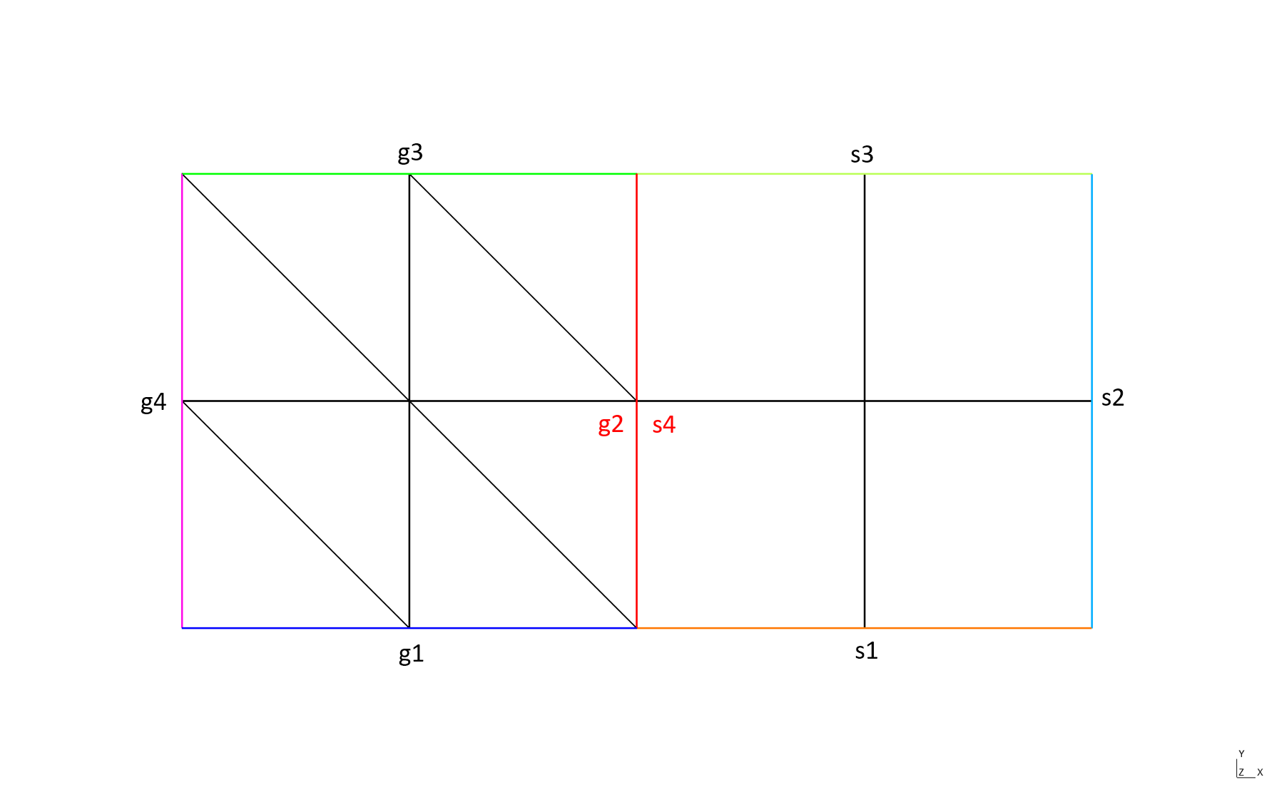
This is the same example but with mergeSharedBoundary set to false:
Mesh mR1R2=merge(mR1P1,mR2Q1, false);
producing the domains:
Domain 'g1' of dimension 1 from mesh 'P1 mesh of [0,1]x[0,1] + Q1 mesh of [1,2]x[0,1]', orientation not computed, 2 elements
 geometric side element 13: side 3 of element 1
 geometric side element 14: side 3 of element 3
Domain 'g2' of dimension 1 from mesh 'P1 mesh of [0,1]x[0,1] + Q1 mesh of [1,2]x[0,1]', orientation not computed, 2 elements
 geometric side element 15: side 2 of element 4
 geometric side element 16: side 2 of element 8
Domain 'g3' of dimension 1 from mesh 'P1 mesh of [0,1]x[0,1] + Q1 mesh of [1,2]x[0,1]', orientation not computed, 2 elements
 geometric side element 17: side 3 of element 6
 geometric side element 18: side 3 of element 8
Domain 'g4' of dimension 1 from mesh 'P1 mesh of [0,1]x[0,1] + Q1 mesh of [1,2]x[0,1]', orientation not computed, 2 elements
 geometric side element 19: side 2 of element 1
 geometric side element 20: side 2 of element 5
Domain 's1' of dimension 1 from mesh 'P1 mesh of [0,1]x[0,1] + Q1 mesh of [1,2]x[0,1]', orientation not computed, 2 elements
 geometric side element 21: side 1 of element 9
 geometric side element 22: side 1 of element 10
Domain 's2' of dimension 1 from mesh 'P1 mesh of [0,1]x[0,1] + Q1 mesh of [1,2]x[0,1]', orientation not computed, 2 elements
 geometric side element 23: side 2 of element 10
 geometric side element 24: side 2 of element 12
Domain 's3' of dimension 1 from mesh 'P1 mesh of [0,1]x[0,1] + Q1 mesh of [1,2]x[0,1]', orientation not computed, 2 elements
 geometric side element 25: side 3 of element 11
 geometric side element 26: side 3 of element 12
Domain 's4' of dimension 1 from mesh 'P1 mesh of [0,1]x[0,1] + Q1 mesh of [1,2]x[0,1]', orientation not computed, 2 elements
 geometric side element 27: side 4 of element 9
 geometric side element 28: side 4 of element 11
Domain 'omega' of dimension 2 from mesh 'P1 mesh of [0,1]x[0,1] + Q1 mesh of [1,2]x[0,1]', orientation not computed, 12 elements
 geometric element 2 (material 0, color 0, twin 0): triangle_Lagrange_1, orientation +0, linear map, measure = 0.125
 ...
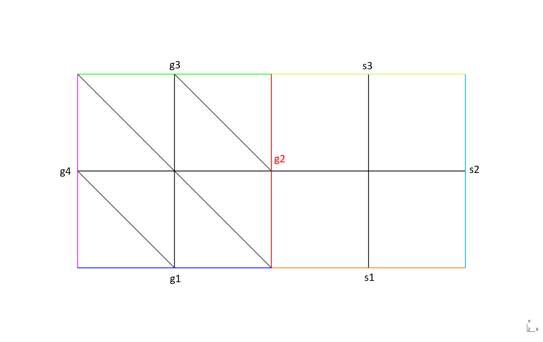
The case when the side domains defining the interface have the same name (here g2):
Rectangle R1(_xmin=0, _xmax=1, _ymin=0, _ymax=1, _nnodes={3,3}, _domain_name="omega", _edge_names={"g1","g2","g3","g4"});
Rectangle R2(_xmin=1, _xmax=2, _ymin=0, _ymax=1, _nnodes={3,3}, _domain_name="omega", _edge_names={"s1","s2","s3","g2"});
Mesh mR1P1(R1, _shape=_triangle, _order=1, _generator=_structured);
Mesh mR2Q1(R2, _shape=_quadrangle, _order=1, _generator=_structured);
Mesh mR1R2=merge(mR1P1,mR2Q1);
provides the following domains:
Domain 'g1' of dimension 1 from mesh 'P1 mesh of [0,1]x[0,1] + Q1 mesh of [1,2]x[0,1]', orientation not computed, 2 elements
 geometric side element 13: side 3 of element 1
 geometric side element 14: side 3 of element 3
Domain 'g2' of dimension 1 from mesh 'P1 mesh of [0,1]x[0,1] + Q1 mesh of [1,2]x[0,1]', orientation not computed, 2 elements
 geometric side element 29: side 2 of element 4, side 4 of element 9
 geometric side element 30: side 2 of element 8, side 4 of element 11
Domain 'g3' of dimension 1 from mesh 'P1 mesh of [0,1]x[0,1] + Q1 mesh of [1,2]x[0,1]', orientation not computed, 2 elements
 geometric side element 17: side 3 of element 6
 geometric side element 18: side 3 of element 8
Domain 'g4' of dimension 1 from mesh 'P1 mesh of [0,1]x[0,1] + Q1 mesh of [1,2]x[0,1]', orientation not computed, 2 elements
 geometric side element 19: side 2 of element 1
 geometric side element 20: side 2 of element 5
Domain 's1' of dimension 1 from mesh 'P1 mesh of [0,1]x[0,1] + Q1 mesh of [1,2]x[0,1]', orientation not computed, 2 elements
 geometric side element 23: side 1 of element 9
 geometric side element 24: side 1 of element 10
Domain 's2' of dimension 1 from mesh 'P1 mesh of [0,1]x[0,1] + Q1 mesh of [1,2]x[0,1]', orientation not computed, 2 elements
 geometric side element 25: side 2 of element 10
 geometric side element 26: side 2 of element 12
Domain 's3' of dimension 1 from mesh 'P1 mesh of [0,1]x[0,1] + Q1 mesh of [1,2]x[0,1]', orientation not computed, 2 elements
 geometric side element 27: side 3 of element 11
 geometric side element 28: side 3 of element 12
 Domain 'omega' of dimension 2 from mesh 'P1 mesh of [0,1]x[0,1] + Q1 mesh of [1,2]x[0,1]', orientation not computed, 12 elements
 geometric element 2 (material 0, color 0, twin 0): triangle_Lagrange_1, orientation +0, linear map, measure = 0.125
 ...
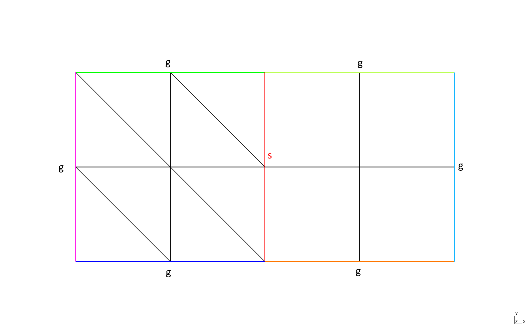
Finally, the case when all boundaries have the same name, except the interface:
Rectangle R1(_xmin=0, _xmax=1, _ymin=0, _ymax=1, _nnodes={3,3}, _domain_name="omega", _edge_names={"g","s","g","g"});
Rectangle R2(_xmin=1, _xmax=2, _ymin=0, _ymax=1, _nnodes={3,3}, _domain_name="omega", _edge_names={"g","g","g","s"});
Mesh mR1P1(R1, _shape=_triangle, _order=1, _generator=_structured);
Mesh mR2Q1(R2, _shape=_quadrangle, _order=1, _generator=_structured);
Mesh mR1R2=merge(mR1P1,mR2Q1);
provides the following domains:
Domain 'g' of dimension 1 from mesh 'P1 mesh of [0,1]x[0,1] + Q1 mesh of [1,2]x[0,1]', orientation not computed, 12 elements
 geometric side element 17: side 3 of element 6
 geometric side element 18: side 3 of element 8
 geometric side element 15: side 2 of element 1
 geometric side element 21: side 3 of element 11
 geometric side element 22: side 3 of element 12
 geometric side element 13: side 3 of element 3
 geometric side element 16: side 2 of element 5
 geometric side element 14: side 3 of element 1
 geometric side element 25: side 2 of element 12
 geometric side element 23: side 2 of element 10
 geometric side element 24: side 1 of element 10
 geometric side element 26: side 1 of element 9
Domain 's' of dimension 1 from mesh 'P1 mesh of [0,1]x[0,1] + Q1 mesh of [1,2]x[0,1]', orientation not computed, 2 elements
 geometric side element 29: side 2 of element 4, side 4 of element 9
 geometric side element 30: side 2 of element 8, side 4 of element 11
Domain 'omega' of dimension 2 from mesh 'P1 mesh of [0,1]x[0,1] + Q1 mesh of [1,2]x[0,1]', orientation not computed, 12 elements
 geometric element 6 (material 0, color 0, twin 0): triangle_Lagrange_1, orientation +0, linear map, measure = 0.125
 ...
Note
As it can be seen in previous examples, an element of an interface domain handles two parent elements whereas an element of a side domain handles only one parent element. For continuous-FE computations, both types of domain can be used but sometimes it may
be important to work with the interface domain. Note that the member function updateParentOfSideElements transforms a side domain into an interface domain.
Miscellaneous#
Some other tools are available build particular meshes.
Mesh of a regular cone-sphere
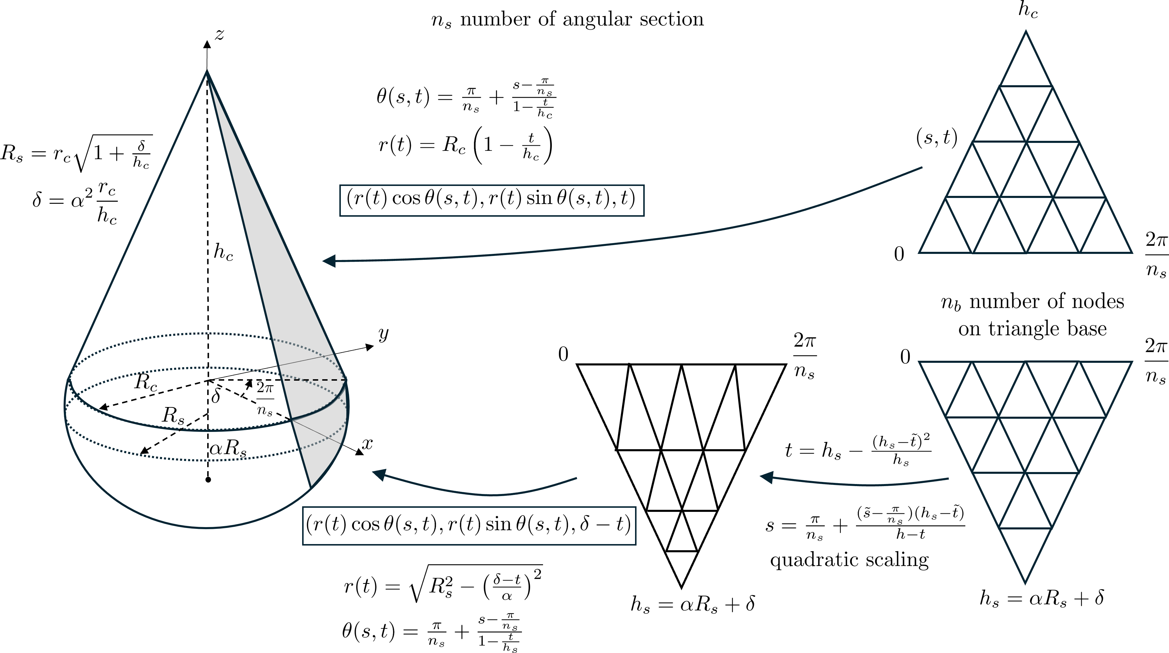
The GMSH tool does not produce satisfying mesh at the cone apex. This is the reason why it is provided a specific tool for meshing the surface of a cone-sphere based on mapping of triangle meshes to cone section or sphere section. A regular cone-sphere is a cone with a spherical cap with a regular (say C1) junction between the cone and the sphere. The following picture illustrates the meshing process:
Mesh RegularConeSphereTri(Point c, Reals ax, Real hc, Real rc, Real obl, Number nbs, Number nbb, MeshGenerator mg, Strings domNames, String interfaceName, Strings apexNames)
where
cis the center of the cone basisaxis the cone axis vectorhcis the cone heightrcis the cone basis radiusoblis the oblateness \(\alpha\) of the sphere (1 means a sphere else an ellipsoid)nbsis the number of sections of sphere and conenbbis the number of nodes on the basis of section of cone or spheremgis the mesh generator to use (_subdiv or _gmsh)domNamesis the list of domain names to give to the cone and the ellipsoidinterfaceNameis the name of the interface between the cone and the ellipsoidapexNamesis the name of the cone apex and the sphere pole
For the sphere, there is a quadratic dilation along the meridians to avoid triangles that are too large at the sphere pole.
The following examples show how to use this function in the two cases of the subdivision generator and the gmsh generator:
Mesh meshConeSphere_subdiv = RegularConeSphereTri(Point(0.,0.,0.), Reals(0.,-1,0.), 4., 1, 0.5, 8, 17, _subdiv, Strings{"cone","sphere"},"circle",Strings{"apex","pole"});
Mesh meshConeSphere_gmsh   = RegularConeSphereTri(Point(0.,0.,0.), Reals(0.,-1,0.), 4., 1, 0.5, 8, 17, _gmsh, Strings{"cone","sphere"},"circle",Strings{"apex","pole"});
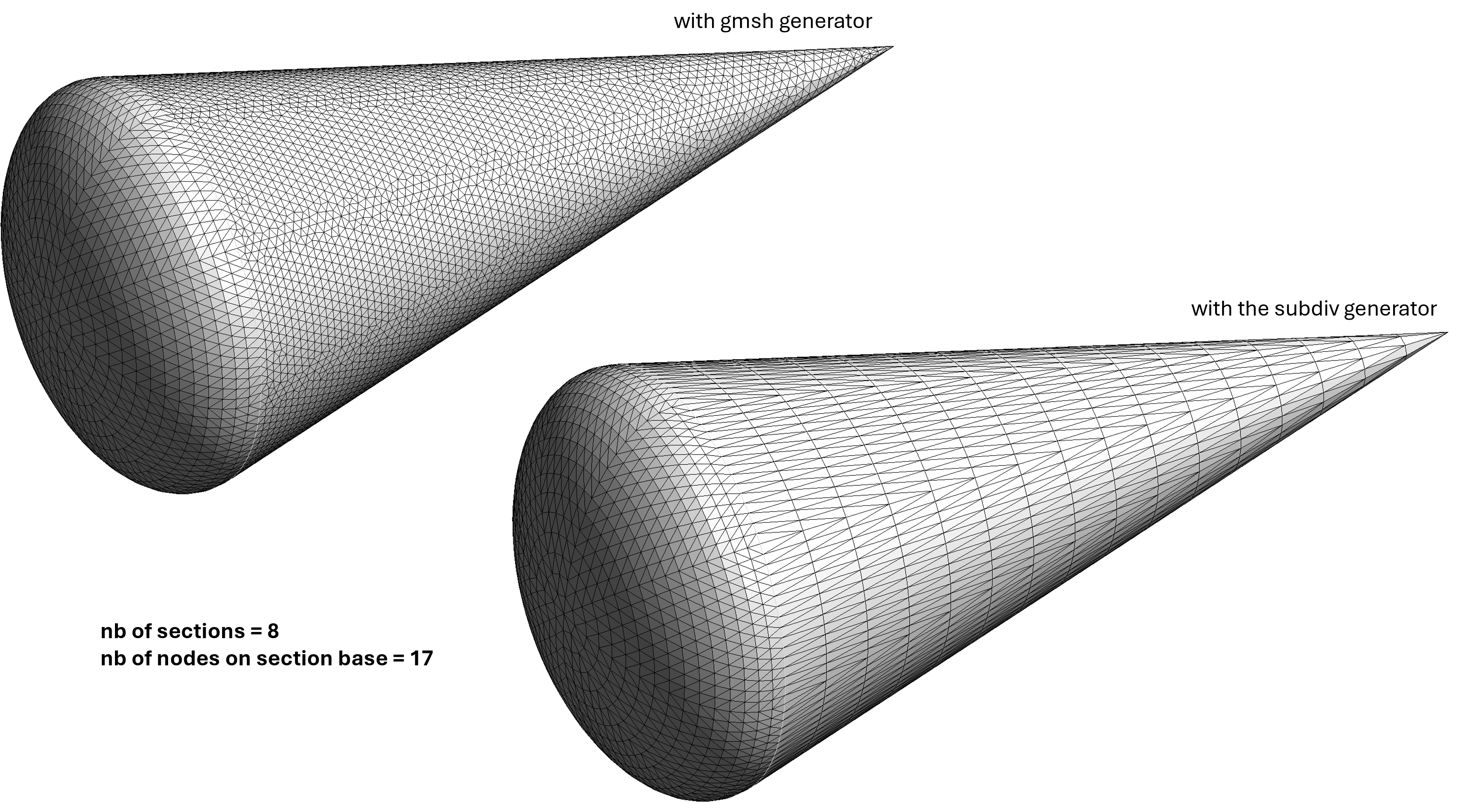
The mesh obtained with the subdivision generator is more regular than the mesh obtained with the gmsh generator, but the latter is more balanced because the number of nodes on cone sides is adjusted according to the mesh size on the cone basis. That is not possible with the subdivision generator! Note that only the surface is meshed with triangles, the volume is not meshed!
It may be of interest for advanced users to take a look on the code performing the cone mesh using the gmsh generator:
Triangle tri_c(_v1=Point(0.,0.,0.), _v2=Point(2*pn,0.,0.), _v3=Point(pn,hc,0.), _nnodes={nb,nl,nl}, _domain_name=nameCone, _edge_names={edgename,"",""});
Mesh meshtri_c(tri_c, _order=1, _generator=_gmsh);
for (auto & v:meshtri_c.nodes) // map triangle to cone section
{
  Real s=v[0], t=v[1];
  Real theta=s, tn=t/hc;
  if (tn<1) theta=pn+(s-pn)/(1-tn);
  Real r = rc*(1-tn);
  v = Point(r*std::cos(theta), r*std::sin(theta), t);
}
meshtri_c.changeDim(3);
Mesh mesh_cone=meshtri_c;
for (Number k=0; k<ns-1;++k)
{
  Mesh meshtrik=rotate3d(meshtri_c, _axis=Reals(0.,0.,1.), _angle=2*pn*(k+1));
  mesh_cone.merge(meshtrik);
}
Cracking mesh#
Cracking a mesh means defining an interface between two domains as a crack; the nodes located on the crack are duplicated, one belonging to a domain and the second to the other domain (see ?).